Network Requirements
- Device1 is connected to PC1, Device2 is connected to PC2 and PC3, and the three PCs are in the same network segment. Device1 and Device2 are interconnected through Trunk ports.
- A static aggregation group is configured between Device1 and Device2 for bandwidth increase, load sharing, and service backup.
Network Topology
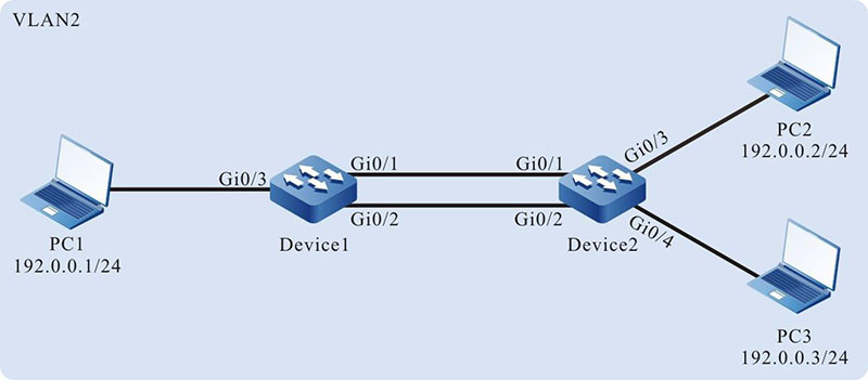
Figure 1-3 Networking for Configuring a Static Aggregation Group
Configuration Steps
Step 1: Create a static aggregation group.
#On Device1, create static aggregation group 1.
|
Device1#configure terminal
Device1(config)#link-aggregation 1 mode manual
|
#On Device2, create static aggregation group 2.
|
Device2#configure terminal
Device2(config)#link-aggregation 1 mode manual
|
Step 2: Add ports into the aggregation group.
#On Device1, add ports gigabitethernet0/1 and gigabitethernet0/2 into aggregation group 1 in Manual mode.
|
Device1(config)#interface gigabitethernet 0/1,0/2
Device1(config-if-range)#link-aggregation 1 manual
Device1(config-if-range)#exit
|
#On Device2, add ports gigabitethernet0/1 and gigabitethernet0/2 into aggregation group 1 in Manual mode.
|
Device2(config)#interface gigabitethernet 0/1,0/2
Device2(config-if-range)#link-aggregation 1 manual
Device2(config-if-range)#exit
|
#After the configuration is completed, check the status of aggregation group 1 on the devices.
Here takes Device1 for example:
Device1#show link-aggregation group 1
 Link Aggregation 1
  Type: switchport
  Mode: Manual
  User: LAC
  Description:
  Peer-description:
  Load balance profile: default
  Number of ports in total: 2
  Number of ports attached: 2
  Root port: gigabitethernet0/1
  gigabitethernet0/1: ATTACHED
  gigabitethernet0/2: ATTACHED
According to the system display, ports gigabitethernet0/1 and gigabitethernet0/2 on Device1 are both in the ATTACHED state in aggregation group 1, and aggregation of aggregation group 1 is successful.

-
For the method of checking Device2, refer to the method of checking Device1.
Step 3: Configure rhe aggregation group to reference the load balance profile.
#On Device1, create the load balance profile linkagg-profile.
|
Device1(config)#load-balance profile linkagg-profile
|
#On Device1, configure the packet load hash-key in the load balance profile linkagg- profile, configure the L2 packet to load by the destination MAC, and configure the IP packet to load by the destination IP.
|
Device1(config-hashprofile)#l2 dst-mac
Device1(config-hashprofile)#ip dst-ip
Device1(config-hashprofile)#active configuration pending
|
#On Device1, configure the load balance profile referenced by aggregation group 1 as linkagg-profile.
|
Device1(config)#interface link-aggregation 1
Device1(config-link-aggregation1)#load-balance profile linkagg-profile
|
Step 4: Configure a VLAN, and configure the link type of the aggregation group and ports.
#On Device1, create VLAN2, configure the link type of aggregation group 1 to Trunk and allow services of VLAN2 to pass, and set Port VLAN ID (PVID) to 2.
|
Device1(config)#vlan 2
Device1(config-vlan2)#exit
Device1(config)#interface link-aggregation 1
Device1(config-link-aggregation1)#switchport mode trunk
Device1(config-link-aggregation1)#switchport trunk allowed vlan add 2
Device1(config-link-aggregation1)#switchport trunk pvid vlan 2
Device1(config-link-aggregation1)#exit
|
#On Device1, configure the link type of port gigabitethernet0/3 to Access and allow services of VLAN2 to pass.
|
Device1(config)#interface gigabitethernet 0/3
Device1(config-if-gigabitethernet0/3)#switchport mode access
Device1(config-if-gigabitethernet0/3)#switchport access vlan 2
Device1(config-if-gigabitethernet0/3)#exit
|
#On Device2, create VLAN2, configure the link type of aggregation group 1 to Trunk and allow services of VLAN2 to pass, and set PVID to 2. (Omitted)
#On Device2, configure the link type of ports gigabitethernet0/3 and gigabitethernet0/4 to Access and allow services of VLAN2 to pass. (Omitted)
Step 5: Check the result.
#On the devices, check the aggregated bandwidth of aggregation group 1.
Device1#show interface link-aggregation 1
link-aggregation 1 configuration information
        Description      :
        Peer-description :
        Status           : Enabled
        Link             : Up
        Act Speed        : 2000
        Act Duplex       : Full
        Port Type        : Nni
        Pvid       : 2
According to the system display, the interface bandwidth of aggregation group 1 on Device1 is 2000 M.
-
For the method of checking Device2, refer to the method of checking Device1.
#On Device1, view the current effective load balancing profile of aggregation group1.
Device1#show link-aggregation group 1
 Link Aggregation 1
  Type: switchport
  Mode: Manual
  User: LAC
  Description:
  Peer-description :
  Load balance profile: linkagg-profile
  Number of ports in total: 2
  Number of ports attached: 2
  Root port: gigabitethernet0/1
  gigabitethernet0/1: ATTACHED
  gigabitethernet0/2: ATTACHED
According to the system display, the current load balance profile of aggregation group 1 is linkagg-profile.
#During the process of service interaction between PC1 and PC2 and PC3, load balancing of data is achieved on the aggregated links. If a link in the aggregation group becomes faulty, the other links provide service backup.
 Switch


