Network Requirements
- The whole PIM multicast domain runs the PIM-SM protocol.
- Loopback0 interface of Device3 is C-BSR. Loopback1 interfaces of Device2 and Device4 are C-RP and the IP addresses are the same.
- Use the IP address of Loopback0 between Device2 and Device4 to set up the MSDP peer connection.
- In the domain, configure multiple RPs with the same address; non-RP device selects the nearest RP used to manage the multicast source and receiver. The RPs exchange the multicast source information via MSDP so that the multicast service of the whole multicast domain can be interacted. If one RP fails, its managed areas are shared by other RPs.
Network Topology
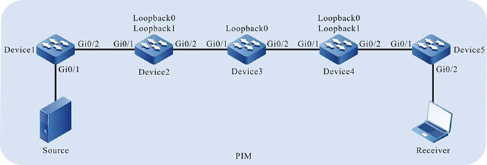
Figure 8-2 Networking of configuring Anycast RP
|
Device
|
Interface
|
VLAN
|
IP address
|
|
Device1
|
Gi0/1
|
2
|
10.1.1.1/24
|
|
|
Gi0/2
|
3
|
10.1.2.1/24
|
|
Device2
|
Gi0/1
|
3
|
10.1.2.2/24
|
|
|
Gi0/2
|
4
|
10.1.3.1/24
|
|
|
Loopback0
|
|
11.11.11.11/32
|
|
|
Loopback1
|
|
55.55.55.55/32
|
|
Device3
|
Gi0/1
|
4
|
10.1.3.2/24
|
|
|
Gi0/2
|
5
|
10.1.4.1/24
|
|
|
Loopback0
|
|
44.44.44.44/32
|
|
Device4
|
Gi0/1
|
5
|
10.1.4.2/24
|
|
|
Gi0/2
|
6
|
10.1.5.1/24
|
|
|
Loopback0
|
|
22.22.22.22/32
|
|
|
Loopback1
|
|
55.55.55.55/32
|
|
Device5
|
Gi0/1
|
6
|
10.1.5.2/24
|
|
|
Gi0/2
|
7
|
10.1.6.1/24
|
|
Source
|
-
|
|
10.1.1.2/24
|
Configuration Steps
Step 1: Configure VLAN and add the port to the corresponding VLAN. (omitted)
Step 2: Configure the IP address of the interface. (omitted)
Step 3: Configure OSPF so that all devices in the network can communicate with each other.
#Configure Device1.
|
Device1#configure terminal
Device1(config)#router ospf 100
Device1(config-ospf)#network 10.1.1.0 0.0.0.255 area 0
Device1(config-ospf)#network 10.1.2.0 0.0.0.255 area 0
Device1(config-ospf)#exit
|
#Configure Device2.
|
Device2#configure terminal
Device2(config)#router ospf 100
Device2(config-ospf)#network 10.1.2.0 0.0.0.255 area 0
Device2(config-ospf)#network 10.1.3.0 0.0.0.255 area 0
Device2(config-ospf)#network 11.11.11.11 0.0.0.0 area 0
Device2(config-ospf)#network 55.55.55.55 0.0.0.0 area 0
Device2(config-ospf)#exit
|
#Configure Device3.
|
Device3#configure terminal
Device3(config)#router ospf 100
Device3(config-ospf)#network 10.1.3.0 0.0.0.255 area 0
Device3(config-ospf)#network 10.1.4.0 0.0.0.255 area 0
Device3(config-ospf)#network 44.44.44.44 0.0.0.0 area 0
Device3(config-ospf)#exit
|
#Configure Device4.
|
Device4#configure terminal
Device4(config)#router ospf 100
Device4(config-ospf)#network 10.1.4.0 0.0.0.255 area 0
Device4(config-ospf)#network 10.1.5.0 0.0.0.255 area 0
Device4(config-ospf)#network 22.22.22.22 0.0.0.0 area 0
Device4(config-ospf)#network 55.55.55.55 0.0.0.0 area 0
Device4(config-ospf)#exit
|
#Configure Device5.
|
Device5#configure terminal
Device5(config)#router ospf 100
Device5(config-ospf)#network 10.1.5.0 0.0.0.255 area 0
Device5(config-ospf)#network 10.1.6.0 0.0.0.255 area 0
Device5(config-ospf)#exit
|
#View the route table of Device5.
Device5#show ip route
Codes: C - connected, S - static, R - RIP, O - OSPF, OE-OSPF External, M - Management
       D - Redirect, E - IRMP, EX - IRMP external, o - SNSP, B - BGP, i-ISIS

Gateway of last resort is not set

O 10.1.1.0/24 [110/5] via 10.1.5.1, 04:04:37, vlan6
O 10.1.2.0/24 [110/4] via 10.1.5.1, 04:05:13, vlan6
O 10.1.3.0/24 [110/3] via 10.1.5.1, 04:17:36, vlan6
O 10.1.4.0/24 [110/2] via 10.1.5.1, 18:19:08, vlan6
C 10.1.5.0/24 is directly connected, 18:22:13, vlan6
C 10.1.6.0/24 is directly connected, 04:32:51, vlan7
O 11.11.11.11/32 [110/4] via 10.1.5.1, 04:17:36, vlan6
O 22.22.22.22/32 [110/2] via 10.1.5.1, 03:56:25, vlan6
O 44.44.44.44/32 [110/3] via 10.1.5.1, 04:13:23, vlan6
O 55.55.55.55/32 [110/2] via 10.1.5.1, 04:17:36, vlan6

-
The viewing method of Device1, Device2, Device3, and Device4 is the same as that of Device5, so the viewing process is omitted.
Step 4: Globally enable the multicast forwarding, enable the multicast protocol PIM-SM on the interface, and configure C-BSR and C-RP.
#Configure Device1.
Globally enable the multicast forwarding, and enable the multicast protocol PIM-SM on the interface.
|
Device1(config)#ip multicast-routing
Device1(config)#interface vlan 2
Device1(config-if-vlan2)#ip pim sparse-mode
Device1(config-if-vlan2)#exit
Device1(config)#interface vlan 3
Device1(config-if-vlan3)#ip pim sparse-mode
Device1(config-if-vlan3)#exit
|
#Configure Device2.
Globally enable the multicast forwarding, enable the multicast protocol PIM-SM on the interface, and configure Loopback1 as C-RP; the multicast group range of the C-RP service is 224.0.0.0/4.
|
Device2(config)#ip multicast-routing
Device2(config)#interface loopback0
Device2(config-if-loopback0)#ip pim sparse-mode
Device2(config-if-loopback0)#exit
Device2(config)#interface loopback1
Device2(config-if-loopback1)#ip pim sparse-mode
Device2(config-if-loopback1)#exit
Device2(config)#interface vlan 3
Device2(config-if-vlan3)#ip pim sparse-mode
Device2(config-if-vlan3)#exit
Device2(config)#interface vlan 4
Device2(config-if-vlan4)#ip pim sparse-mode
Device2(config-if-vlan4)#exit
Device2(config)#ip pim rp-candidate loopback1
|
#Configure Device3.
Globally enable the multicast forwarding, enable the multicast protocol PIM-SM on the interface, and configure Loopback0 as C-BSR.
|
Device3(config)#ip multicast-routing
Device3(config)#interface loopback0
Device3(config-if-loopback0)#ip pim sparse-mode
Device3(config-if-loopback0)#exit
Device3(config)#interface vlan 4
Device3(config-if-vlan4)#ip pim sparse-mode
Device3(config-if-vlan4)#exit
Device3(config)#interface vlan 5
Device3(config-if-vlan5)#ip pim sparse-mode
Device3(config-if-vlan5)#exit
Device3(config)#ip pim bsr-candidate loopback0
|
#Configure Device4.
Globally enable the multicast forwarding, enable the multicast protocol PIM-SM on the interface, and configure Loopback1 as C-RP; the multicast group range of the C-RP service is 224.0.0.0/4.
|
Device4(config)#ip multicast-routing
Device4(config)#interface loopback0
Device4(config-if-loopback0)#ip pim sparse-mode
Device4(config-if-loopback0)#exit
Device4(config)#interface loopback1
Device4(config-if-loopback1)#ip pim sparse-mode
Device4(config-if-loopback1)#exit
Device4(config)#interface vlan 5
Device4(config-if-vlan5)#ip pim sparse-mode
Device4(config-if-vlan5)#exit
Device4(config)#interface vlan 6
Device4(config-if-vlan6)#ip pim sparse-mode
Device4(config-if-vlan6)#exit
Device4(config)#ip pim rp-candidate loopback1
|
#Configure Device5. Globally enable the multicast forwarding and enable the multicast protocol PIM-SM on the interface.
|
Device5(config)#ip multicast-routing
Device5(config)#interface vlan 6
Device5(config-if-vlan6)#ip pim sparse-mode
Device5(config-if-vlan6)#exit
Device5(config)#interface vlan 7
Device5(config-if-vlan7)#ip pim sparse-mode
Device5(config-if-vlan7)#exit
|
#View the information of the interface enabled with the PIM-SM protocol on Device5 and the PIM-SM neighbor information.
Device5#show ip pim interface

PIM Interface Table: PIM VRF Name: Default
Total 3 Interface entries
Total 0 External Interface entry
Total 0 Sparse-Dense Mode Interface entry

Address     Interface            VIF      Ver/      VIF      Nbr       DR       DR
BSR CISCO Neighbor
                                 Index   Mode   Flag        Count        Pri
Border Neighbor Filter
10.1.5.2     register_vif0       1       v2/S    UP
10.1.5.2     vlan6               0       v2/S    UP    1      1	10.1.5.2
FALSE FALSE
10.1.6.1     vlan7               2       v2/S    UP    0      1  10.1.6.1 FALSE FALSE

Device5#show ip pim neighbor
PIM Neighbor Table:
PIM VRF Name: Default
Total 1 Neighbor entry

Neighbor     Interface    Uptime/Expires    Ver DR
Address                                         Priority/Mode
10.1.5.1     vlan6        18:37:22/00:01:45 v2  1 /
#View the BSR and RP information of Device5.
Device5#show ip pim bsr-router
PIMv2 Bootstrap information
PIM VRF Name: Default
  BSR address: 44.44.44.44
  BSR Priority: 0
  Hash mask length: 10
  Up time: 04:36:44
  Expiry time: 00:01:35
  Role: Non-candidate BSR
  State: Accept Preferred

Device5#show ip pim rp mapping
PIM Group-to-RP Mappings Table:
PIM VRF Name: Default
Total 1 RP set entry
Total 1 RP entry

  Group(s): 224.0.0.0/4
  RP count: 1
    RP: 55.55.55.55
      Info source: 44.44.44.44, via bootstrap, priority 192
      Up time: 04:36:44
      Expiry time: 00:01:53
-
The viewing method of Device1, Device2, Device3, and Device4 is the same as that of Device5, so the viewing process is omitted.
Step 5: Configure MSDP.
#Configure Device2.
Configure setting up the non-direct-connected MSDP peer connection via Loopback0 with Loopback0 of Device4; enable the function of actively sending the SA request packet to the specified peer; configure the RP address in the SA packet as the IP address of Loopback0; configure using the RFC3618 rule to perform the RPF check for the MSDP packet.
|
Device2(config)#ip msdp peer 22.22.22.22 connect-source loopback0
Device2(config)#ip msdp sa-request 22.22.22.22
Device2(config)#ip msdp originator-id loopback0
Device2(config)#ip msdp rpf rfc3618
|
#Configure Device4.
Configure setting up the non-direct-connected MSDP peer connection via Loopback0 with Loopback0 of Device2; enable the function of actively sending the SA request packet to the specified peer; configure the RP address in the SA packet as the IP address of Loopback0; configure using the RFC3618 rule to perform the RPF check for the MSDP packet.
|
Device4(config)#ip msdp peer 11.11.11.11 connect-source loopback0
Device4(config)#ip msdp sa-request 11.11.11.11
Device4(config)#ip msdp originator-id loopback0
Device4(config)#ip msdp rpf rfc3618
|
#View the MSDP peer connection status and details of Device4.
Device4#show ip msdp summary
MSDP Peer Status Summary
Total 1 Peer entry
Peer Address     AS  State  Reset   Uptime/Downtime
11.11.11.11      ?   Up     0       05:49:35

Device4#show ip msdp peer
MSDP Peer 11.11.11.11, AS ?
  Connection status:
    State: Established, Resets: 0, Connection source: loopback0
    Uptime(Downtime): 05:49:39, Message sent/received: 352/528
    Connection and counters cleared 05:53:24 ago
    Local Address of connection: 22.22.22.22
    Remote Address of connection: 11.11.11.11
    Local Port: 639, Remote Port: 1053
  SA-Requests:
    Input filter: none
    Sending SA-Requests to peer: enabled
  SA:
    Input filter: none
  Message counters:
    RPF Failure count: 3
    SA Messages in/out: 348/0
    SA Requests in/out: 0/3
    SA Responses in/out: 2/0
  Data Packets in/out: 0/0
You can see that Device4 and Device2 set up the MSDP peer connection successfully.
-
The viewing method of Device2 is the same as that of Device4, so the viewing process is omitted.
Step 6: Check the result.
# Source sends the multicast service packet with multicast group 225.1.1.1.
#View the MSDP SA cache information of Device2.
Device2#show ip msdp sa-cache
MSDP Source-Active Cache - 1 entries
(10.1.1.2, 225.1.1.1), RP 55.55.55.55, Originated, 00:03:34/00:05:43
You can see that Device2 generates and caches the SA packet. The multicast source address in the SA packet is 10.1.1.2; the multicast group address is 225.1.1.1; the RP address is 55.55.55.55.
#View the MSDP SA cache information and RPF check table of Device4.
Device4#show ip msdp sa-cache
MSDP Source-Active Cache - 1 entries
(10.1.1.2, 225.1.1.1), RP 11.11.11.11, Recv From Peer 11.11.11.11, 00:07:02/00:05:58

Device4#show ip msdp rpf
Destination   Nexthop     Nexthop       Nexthop Metric Pref
Address       Address     From          RefCnt
10.1.4.1      0.0.0.0     0.0.0.0       1       10     0
11.11.11.11   10.1.4.1    55.55.55.55   3       3      110
55.55.55.55   0.0.0.0     0.0.0.0       2       1      0
You can see that Device4 receives and caches the SA packet. The SA packet is from the peer 11.11.11.11. The multicast source address in the packet is 10.1.1.2; the multicast group address is 225.1.1.1; the RP address is 11.11.11.11.
-
If ip msdp originator-id is configured on the source RP and when it sends the SA packet to MSDP peer, it replaces the RP address in the packet with the IP address of the specified interface.
#View the PIM-SM multicast route table of Device2.
Device2#show ip pim mroute
IP Multicast Routing Table:
PIM VRF Name: Default
Total 0 (*,*,RP) entry
Total 0 (*,G) entry
Total 1 (S,G) entry
Total 1 (S,G,rpt) entry
Total 0 FCR entry
Up timer/Expiry timer

(10.1.1.2, 225.1.1.1)
Up time: 00:01:14
KAT time: 00:03:23
RPF nbr: 10.1.2.1
RPF idx: vlan3
SPT bit: FALSE
Flags:
Upstream State: NOT JOINED
  Local interface list:
  Joined interface list:
  Asserted interface list:
  Outgoing interface list:
  Packet count 0

(10.1.1.2, 225.1.1.1, rpt)
Up time: 00:01:14 RP: 55.55.55.55
Flags:
  RPF SGRPT XG EQUAL
Upstream State: RPT NOT JOINED
  Local interface list:
  Pruned interface list:
  Outgoing interface list:
#View the PIM-SM multicast route table of Device4.
Device4#show ip pim mroute
IP Multicast Routing Table:
PIM VRF Name: Default
Total 0 (*,*,RP) entry
Total 0 (*,G) entry
Total 0 (S,G) entry
Total 0 (S,G,rpt) entry
Total 0 FCR entry
Up timer/Expiry timer
You can see that there is (10.1.1.2, 225.1.1.1) entry on Device2 and no (10.1.1.2, 225.1.1.1) entry on Device4. It indicates that Source initiates the PIM-SM register to the nearest RP, that is, Device2.
#Receiver sends the IGMPv2 member report packet to add to multicast group 225.1.1.1.
#View the multicast member table on Device5.
Device5#show ip igmp groups IGMP Connected Group Membership Total 1 groups
Group Address   Interface  Uptime     Expires    Last Reporter V1 Expires V2 Expires
225.1.1.1       vlan7      00:00:12   00:04:12   10.1.6.2      stopped
#View the PIM-SM multicast route table of Device2.
Device2#show ip pim mroute
IP Multicast Routing Table:
PIM VRF Name: Default
Total 0 (*,*,RP) entry
Total 0 (*,G) entry
Total 1 (S,G) entry
Total 1 (S,G,rpt) entry
Total 0 FCR entry
Up timer/Expiry timer

(10.1.1.2, 225.1.1.1)
Up time: 00:19:01
KAT time: 00:03:14
RPF nbr: 10.1.2.1
RPF idx: vlan3
SPT bit: TRUE
Flags:
  JOIN DESIRED
Upstream State: JOINED
  Local interface list:
  Joined interface list:
    vlan4 00:02:56/00:02:34
  Asserted interface list:
  Outgoing interface list:
    vlan4
  Packet count 1136269

(10.1.1.2, 225.1.1.1, rpt)
Up time: 00:19:01 RP: 55.55.55.55
Flags:
  RPF SGRPT XG EQUAL
Upstream State: RPT NOT JOINED
#View the PIM-SM multicast route table of Device4.
Device4#show ip pim mroute
IP Multicast Routing Table:
PIM VRF Name: Default
Total 0 (*,*,RP) entry
Total 1 (*,G) entry
Total 1 (S,G) entry
Total 1 (S,G,rpt) entry
Total 0 FCR entry
Up timer/Expiry timer

(*, 225.1.1.1)
Up time: 00:05:54
RP: 55.55.55.55
RPF nbr: 0.0.0.0
RPF idx: None
Flags:
  JOIN DESIRED
Upstream State: JOINED
  Local interface list:
  Joined interface list:
    vlan6 00:05:54/00:02:36
  Asserted interface list:


(10.1.1.2, 225.1.1.1)
Up time: 00:05:54
KAT time: 00:03:22
RPF nbr: 10.1.4.1
RPF idx: vlan5
SPT bit: TRUE
Flags:
  JOIN DESIRED
Upstream State: JOINED
  Local interface list:
  Joined interface list:
    vlan6 00:05:54/00:02:37
  Asserted interface list:
  Outgoing interface list:
    vlan6
  Packet count 2172581

(10.1.1.2, 225.1.1.1, rpt)
Up time: 00:05:54
RP: 55.55.55.55
Flags:
  RPT JOIN DESIRED
  PRUNE DESIRED
  RPF SGRPT XG EQUAL
Upstream State: PRUNED
  Local interface list:
  Pruned interface list:
  Outgoing interface list:
    vlan6
You can see that there is (*,225.1.1.1) entry on Device4 and no (*,225.1.1.1) entry on Device2. It indicates that Source initiates the PIM-SM adding to the nearest RP, that is, Device4.
#Receiver can receive the multicast service packet with multicast group 225.1.1.1 sent by Source.
 Switch


