Network Requirements
- Device1 configures multicast routing protocol.
- Device2 enables IGMP snooping, configures multicast receiving control and applies to the corresponding port.
- Multicast Server sends the multicast service packet; PC1 and PC2 can receive the multicast service packet.
Network Topology
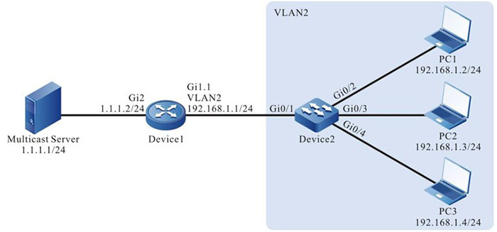
Figure 2-2 Network topology of configuring multicast receiving control
Configuration Steps
Step 1: Device1 configures the interface IP address and enables the multicast route protocol. (omitted)
Step 2: Configure Device2.
#Create VLAN2 on Device2.
|
Device2#configure terminal
Device2(config)#vlan 2
Device2(config-vlan2)#exit
|
#Configure the link type of the port gigabitethernet0/2-gigabitethernet0/4 on Device2 as Access, permitting the services of VLAN2 to pass.
|
Device2#configure terminal
Device2(config)#vlan 2
Device2(config-vlan2)#exit
Device2(config)#interface gigabitethernet 0/2-0/4
Device2(config-if-range)#switchport access vlan 2
Device2(config-if-range)#exit
|
#Configure the link type of port gigabitethernet0/1 on Device2 as Trunk, permitting the services of VLAN2 to pass; PVID is configured as 1.
|
Device2(config)#interface gigabitethernet 0/1
Device2(config-if-gigabitethernet0/1)#switchport mode trunk
Device2(config-if-gigabitethernet0/1)#switchport trunk allowed vlan add 2
Device2(config-if-gigabitethernet0/1)#switchport trunk pvid vlan 1
Device2(config-if-gigabitethernet0/1)#exit
|
#Enable IGMP snooping.
|
Device2(config)#ip igmp snooping
Device2(config)#ip igmp snooping vlan 2
|
#Configure multicast receiving control policy profile1, permits to add multicast group 224.1.1.1 and apply to port gigabitethernet0/2.
|
Device2(config)#ip igmp profile 1
Device2(config-igmp-profile)#permit 224.1.1.1
Device2(config-igmp-profile)#exit
Device2(config)#interface gigabitethernet 0/2
Device2(config-if-gigabitethernet0/2)#ip igmp filter 1
Device2(config-if-gigabitethernet0/2)#exit
|
#Configure multicast receiving control policy profile2, preview multicast group 224.1.1.1 and apply to port gigabitethernet0/3.
|
Device2(config)#ip igmp profile 2
Device2(config-igmp-profile)#preview 224.1.1.1
Device2(config-igmp-profile)#exit
Device2(config)#interface gigabitethernet 0/3
Device2(config-if-gigabitethernet0/3)#ip igmp filter 2
Device2(config-if-gigabitethernet0/3)#exit
|
#Configure multicast receiving control policy profile3, refuse adding to multicast group 224.1.1.1 and apply to port gigabitethernet0/4.
|
Device2(config)#ip igmp profile 3
Device2(config-igmp-profile)#permit all
Device2(config-igmp-profile)#deny 224.1.1.1
Device2(config-igmp-profile)#exit
Device2(config)#interface gigabitethernet 0/4
Device2(config-if-gigabitethernet0/4)#ip igmp filter 3
Device2(config-if-gigabitethernet0/4)#exit
|
Step 3: Check the result.
#PC1, PC2 and PC3 send IGMPv2 member report packet to add to multicast group 224.1.1.1.
#View multicast member table of Device2.
Device2#show ip igmp snooping groups
IGMP Snooping Group Membership
Total 2 groups

VLAN ID Interface Name Group Address Expires   Last Reporter V1 Expires V2 Expires Uptime
---------------------------------------------------------------------------------------
2       gi0/2          224.1.1.1     00:04:19  192.168.1.2    stopped              00:00:01
2       gi0/3          224.1.1.1     00:04:19  192.168.1.3     stopped             00:00:01
PC1 and PC2 can add to multicast group 224.1.1.1; PC3 does not add to multicast group 224.1.1.1.
# Multicast Server sends the multicast service packet with destination address 224.1.1.1.
PC1 and PC2 can correctly receive the multicast service packet; PC3 cannot receive the multicast service packet.
#After waiting for 10s, view the multicast member table of Device2 and multicast receiving control information of gigabitethernet0/3.
Device2#show ip igmp snooping groups
IGMP Snooping Group Membership
Total 1 group

VLAN ID Interface Name Group Address Expires   Last Reporter V1 Expires V2 Expires Uptime
-------------------------------------------------------------------------------------------
2       gi0/2          224.1.1.1     00:04:10  192.168.1.2   stopped               00:00:10

Device2#show multicast control interface gigabitethernet 0/3
ip multicast control gigabitethernet0/3 vlan 2 information
 	 profile: 2
group right information:
 preview: 224.1.1.1 preview information:
  preview count: 3
  preview count remain: 2
  preview time: 10 (s)
  preview interval: 60 (s) group information:
  group: 224.1.1.1
    uptime: 00:00:10
    next preview time remain: 00:00:60
After the preview time of port gigabitethernet0/3 arrives (after 10s), the group member entry is deleted; PC1 can correctly receive the multicast service packet; PC2 and PC2 cannot receive the multicast service packet.
 Switch


