Network Requirements
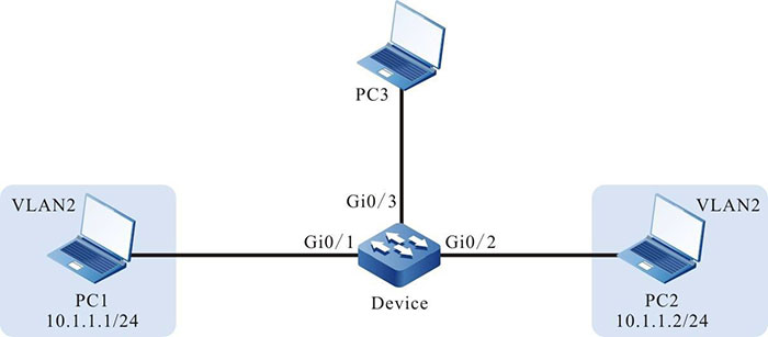
- PC1, PC2 and PC3 are connected with Device; PC1 and PC2 communicate in VLAN2.
- Configure the flow mirror function on Device, realizing that PC3 monitor the packets received by port gigabitethernet0/1 of Device.
Network Topology

Figure 1-11 Networking of configuring the flow mirror
Configuration Steps
Step 1: Configure the link type of the VLAN and port.
#Create VLAN2 on Device.
|
Device#configure terminal
Device(config)#vlan 2
Device(config-vlan2)#exit
|
#Configure the link type of port gigabitethernet0/1 and gigabitethernet0/2 on Device as Access and permit the services of VLAN2 to pass.
|
Device(config)#interface gigabitethernet 0/1-0/2
Device(config-if-range)#switchport mode access
Device(config-if-range)#switchport access vlan 2
Device(config-if-range)#exit
|
Step 2: Configure the flow mirror function.
#Configure the L3 action group named mirror and mirror the packet to port gigabitethernet0/3.
|
Device(config)#l3-action-group mirror
Device(config-action-group)#mirror interface gigabitethernet 0/3
Device(config-action-group)#exit
|
Step 3: Configure the counter function.
#Configure the egress action group named count, counting the number of the packets.
|
Device(config)#egr-action-group count
Device(config-egract-group)#count all-colors
Device(config-egract-group)#exit
|
Step 4: Configure the IP standard ACL.
#Configure the IP standard ACL with serial number 1 on Device.
|
Device(config)#ip access-list standard 1
|
#Configure binding the rule with the L3 action group named mirror, realizing that all packets are mirrored to port gigabitethernet0/3.
|
Device(config-std-nacl)#permit any l3-action-group mirror
Device(config-std-nacl)#commit
Device(config-std-nacl)#exit
|
#Configure the IP standard ACL with serial number 2 on Device.
|
Device(config)#ip access-list standard 2
|
#Configure binding the rule with the egress action group named count, counting all packets.
|
Device(config-std-nacl)#permit any egr-action-group count
Device(config-std-nacl)#commit
Device(config-std-nacl)#exit
|
Step 5: Configure applying the IP standard ACL.
#Apply the IP standard ACL with serial number 1 to the ingress direction of port gigabitethernet0/1 on Device.
|
Device(config)#interface gigabitethernet 0/1
Device(config-if-gigabitethernet0/1)#ip access-group 1 in
Device(config-if-gigabitethernet0/1)#exit
|
#Apply the IP standard ACL with serial number 2 to the egress direction of port gigabitethernet0/3 on Device.
|
Device(config)#interface gigabitethernet 0/3
Device(config-if-gigabitethernet0/3)#ip access-group 2 out
Device(config-if-gigabitethernet0/3)#exit
|
#View the information of the ACL applied to the port on Device.
Device#show acl-object interface
-----------Interface-----Bind-----Instance
Interface----------------Direction----AclType----AclName
gi0/1                    IN           IP         1
gi0/3                    OUT          IP         2
Step 6: Check the result.
#When PC1 and PC2 communicate with each other, we can capture the packets received by port gigabitethernet0/1 on PC3.
#View the number of the packets measured by the counter on Device.
Device#show traffic-count inst-interface gigabitethernet 0/3 ip-out
Interface           Instance_type                Acl_name		Frame_gap
gigabitethernet0/3  Ip Acl Bind Interface Out    2     	 	    No
--------------------------------------------------------------------
seq                 :                            10
counter_mode        :                            count all color
all packets number  :                            5
all packets byte    :                            640
We can see that there are five packets measured at the egress direction of port gigabitethernet0/3.
 Switch
 Wifi - Access Point
 Firewall
 Router
 Module Quang
![Module Quang Cisco]() Module Quang Cisco
Module Quang Cisco![Module quang HPE]() Module quang HPE
Module quang HPE![Module quang Maipu]() Module quang Maipu
Module quang Maipu![Module quang Brocade]() Module quang Brocade
Module quang Brocade![Module quang Fortinet]() Module quang Fortinet
Module quang Fortinet![Module quang Aruba]() Module quang Aruba
Module quang Aruba![Module quang OEM]() Module quang OEM
Module quang OEM![Module quang Juniper]() Module quang Juniper
Module quang Juniper![Module quang Dell]() Module quang Dell
Module quang Dell![Module quang Palo Alto]() Module quang Palo Alto
Module quang Palo Alto![Module quang Huawei]() Module quang Huawei
Module quang Huawei![Module quang Arista]() Module quang Arista
Module quang Arista![Module quang F5]() Module quang F5
Module quang F5![Module quang H3C]() Module quang H3C
Module quang H3C![Module Quang Allied Telesis]() Module Quang Allied Telesis
Module Quang Allied Telesis![Module quang SonicWall]() Module quang SonicWall
Module quang SonicWall![Module quang Mikrotik]() Module quang Mikrotik
Module quang Mikrotik![Module quang Handar]() Module quang Handar
Module quang Handar Máy chủ (Server)
 Thiết bị lưu trữ (SAN, NAS)
 Load Balancing
 Video Conferencing
 Phụ kiện máy chủ
 Thiết Bị IoT
 Phụ Kiện Mạng


.png)


