Configure VRRP Load Balance
Network Requirements
- Device1 and Device2 belong to two VRRP groups at the same time; Device1 is Master in group1 and Backup in group2; Device2 is Backup in group1 and Master in group2.
- PC1 forwards data via Device1 and PC2 forwards data via Device2, realizing the load balance.
Network Topology
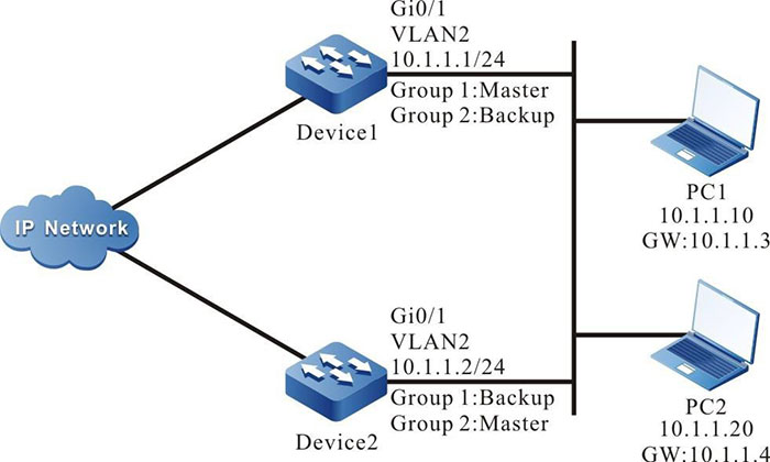
Figure 5-7 VRRP load balance networking
Configuration Steps
Step 1: Configure VLAN and add the port to the corresponding VLAN.(Omitted)
Step 2: Configure the IP address of the interface.(Omitted)
Step 3: Create the VRRP group 1.
#Configure the VRRP group 1 on Device1; the virtual IP address is 10.1.1.3 and the priority is 110.
|
Device1#configure terminal
Device1(config)#interface vlan 2
Device1(config-if-vlan2)#vrrp 1 ip 10.1.1.3
Device1(config-if-vlan2)#vrrp 1 priority 110
Device1(config-if-vlan2)#exit
|
#Configure the VRRP group 1 on Device2; the virtual IP address is 10.1.1.3.
|
Device2#configure terminal
Device2(config)#interface vlan 2
Device2(config-if-vlan2)#vrrp 1 ip 10.1.1.3
Device2(config-if-vlan2)#exit
|
Step 4: Create VRRP group 2.
#Configure the virtual IP address of VRRP group2 as 10.1.1.4 on Device1.
|
Device1(config)#interface vlan 2
Device1(config-if-vlan2)#vrrp 2 ip 10.1.1.4
Device1(config-if-vlan2)#exit
|
#Configure the virtual IP address of VRRP group2 as 10.1.1.4 on Device2 and configure the priority as 110.
|
Device2(config)#interface vlan 2
Device2(config-if-vlan2)#vrrp 2 ip 10.1.1.4
Device2(config-if-vlan2)#vrrp 2 priority 110
Device2(config-if-vlan2)#exit
|
Step 5: Check the result.
#View the status of VRRP in group1 and group2 on Device1.
Device1#show vrrp
Interface vlan2 (Flags 0x1)
  Pri-addr : 10.1.1.1
  Vrf : 0
  Virtual router : 1
    Virtual IP address : 10.1.1.3
    Virtual MAC address : 00-00-5e-00-01-01 , installed into HW
    Depend prefix:10.1.1.1/24
    State : Master
    Normal priority : 110
    Currnet priority : 110
    Priority reduced : 0
    Preempt-mode : YES
    Advertise-interval : 1
    Authentication Mode : None

  Virtual router : 2
    Virtual IP address : 10.1.1.4
    Virtual MAC address : 00-00-5e-00-01-02
    Depend prefix:10.1.1.1/24
    State : Backup
    Master addr : 10.1.1.2
    Normal priority : 100
    Currnet priority : 100
    Priority reduced : 0
    Preempt-mode : YES
    Advertise-interval : 1
    Authentication Mode : None
#View the status of VRRP in group1 and group2 on Device2.
Device2#show vrrp
Interface vlan2 (Flags 0x1)
  Pri-addr : 10.1.1.2
  Vrf : 0
  Virtual router : 1
    Virtual IP address : 10.1.1.3
    Virtual MAC address : 00-00-5e-00-01-01
    Depend prefix:10.1.1.2/24
    State : Backup
    Master addr : 10.1.1.1
    Normal priority : 100
    Currnet priority : 100
    Priority reduced : 0
    Preempt-mode : YES
    Advertise-interval : 1
    Authentication Mode : None

  Virtual router : 2
    Virtual IP address : 10.1.1.4
    Virtual MAC address : 00-00-5e-00-01-02 , installed into HW
    Depend prefix:10.1.1.2/24
    State : Master
    Normal priority : 110
    Currnet priority : 110
    Priority reduced : 0
    Preempt-mode : YES
    Advertise-interval : 1
    Authentication Mode : None
We can see that Device1 serves as Master of VRRP group1 and Backup of VRRP group2. In contrast with Device1, Device2 serves as Master of VRRP group 2 and Backup of VRRP group 1. When one device fails, two PCs forward data via the other device. This realizes the load balance and backup for each other.
 Switch


