Network Requirements
- Leaf1 and leaf2 serve as VTEP to create the VXLAN instance.
- Leaf1 and Leaf2 set up the static VXLAN tunnel through loopback interface.
- The VXLAN tunnel is established to realize the VM interworking between server 1 and server2 of the same network segment.
Network Topology
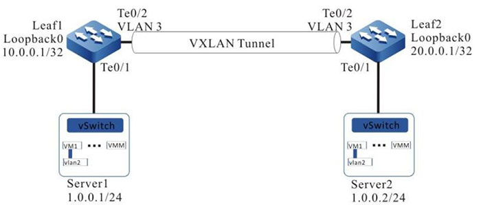
Figure 1-1 Networking of configuring the static VXLAN to realize the L2 intercommuniation
Configuration Steps
Step 1: Configure VLAN, and add the port to the corresponding VLAN (omitted).
Step 2: Configure the IP address of the interface.
#Configure Leaf1.
|
Leaf1(config)#interface loopback 0
Leaf1(config-if-loopback0)#ip address 10.0.0.1 255.255.255.255
Leaf1(config-if-loopback0)#exit
Leaf1(config)#interface vlan 3
Leaf1(config-if-vlan3)#ip address 2.0.0.1 255.255.255.0
Leaf1(config-if-vlan3)#exit
|
#Configure Leaf2.
|
Leaf2(config)#interface loopback 0
Leaf2(config-if-loopback0)#ip address 20.0.0.1 255.255.255.255
Leaf2(config-if-loopback0)#exit
Leaf2(config)#interface vlan 3
Leaf2(config-if-vlan3)#ip address 2.0.0.2 255.255.255.0
Leaf2(config-if-vlan3)#exit
|
Step 3: Configure OSPF, making the Loopback routes between the devices reachable.
#Configure Leaf1.
|
Leaf1#configure terminal
Leaf1(config)#router ospf 100
Leaf1(config-ospf)#network 10.0.0.1 0.0.0.0 area 0
Leaf1(config-ospf)#network 2.0.0.0 0.0.0.255 area 0
Leaf1(config-ospf)#exit
|
#Configure Leaf2.
|
Leaf2#configure terminal
Leaf2(config)#router ospf 100
Leaf2(config-ospf)#network 20.0.0.1 0.0.0.0 area 0
Leaf2(config-ospf)#network 2.0.0.0 0.0.0.255 area 0
Leaf2(config-ospf)#exit
|
#View the route table of Leaf1.
Leaf1#show ip route
Codes: C - connected, S - static, R - RIP, O - OSPF, OE-OSPF External, M - Management
       D - Redirect, E - IRMP, EX - IRMP external, o - SNSP, B - BGP, i-ISIS

Gateway of last resort is not set

C 2.0.0.0/24 is directly connected, 00:05:40, vlan3
C 127.0.0.0/8 is directly connected, 1d:21:38:36, lo0
C 10.0.0.1/32 is directly connected, 00:06:34, loopback0
O 20.0.0.1/32 [110/2] via 2.0.0.2, 00:00:05, vlan3
#View the route table of Leaf2.
Leaf2#show ip route
Codes: C - connected, S - static, R - RIP, O - OSPF, OE-OSPF External, M Management
       D - Redirect, E - IRMP, EX - IRMP external, o - SNSP, B BGP, i-ISIS

Gateway of last resort is not set

C 2.0.0.0/24 is directly connected, 00:06:43, vlan3
C 127.0.0.0/8 is directly connected, 1w3d:03:35:57, lo0
O 10.0.0.1/32 [110/2] via 2.0.0.1, 00:02:36, vlan3
C 20.0.0.1/32 is directly connected, 00:07:07, loopback0
It can be seen that leaf1 and leaf2 learn the route of the peer loop port by running the OSPF protocol, which is prepared for leaf1 and leaf2 to establish IBGP neighbors through the loopback port.
Step 4: Configure VXLAN and associate VNID, and configure EVPN address family to add ports of leaf1 and leaf2 to VXLAN.
#Configure Leaf1.
|
Leaf1(config)# vxlan 100
Leaf1(config-vxlan-100)#vxlan vnid 100
Leaf1(config-vxlan-100)#vxlan interface-vlan 2
Leaf1(config-vxlan-100)#exit
|
#Configure Leaf2.
|
Leaf2(config)# vxlan 100
Leaf2(config-vxlan-100)#vxlan vnid 100
Leaf2(config-vxlan-100)#vxlan interface-vlan 2
Leaf2(config-vxlan-100)# interface tengigabitethernet 0/1
Leaf2(config-if-gigabitethernet0/1)#switchport access vlan 2
Leaf2(config-vxlan-100)#exit
|
#View the VXLAN information of Leaf1.
Leaf1#show vxlan 100 config
vxlan 100
 vxlan vnid 100
 vxlan internal-vlan vlan 2
 exit
#View the VXLAN information of Leaf2.
Leaf2#show vxlan 100 config
vxlan 100
 vxlan vnid 100
 vxlan interna-vlan interface vlan 2
 exit
Step 5: Configure the static VXLAN tunnel.
#Configure the NVE interface of Leaf1 and the static header replication members of the corresponding VXLAN.
|
Leaf1(config)#interface nve 1
Leaf1(config-if-nve1)#source 10.0.0.1
Leaf1(config-if-nve1)#vxlan 100 ingress-replication peer 20.0.0.1
Leaf1(config-if-nve1)#exit
|
#Configure the NVE interface of Leaf2 and the static header replication members of the corresponding VXLAN.
|
Leaf2(config)#interface nve 1
Leaf2(config-if-nve1)#source 20.0.0.1
Leaf2(config-if-nve1)#vxlan 100 ingress-replication peer 10.0.0.1
Leaf2(config-if-nve1)#exit
|
#View the tunnel information and VXLAN session of Leaf1.
Leaf1# show vxlan tunnel Number of vxlan tunnel: 1
---- ---------  ---------  -----------   -----
NO.  TunnelID   Source     Destination   State
---- ---------  ---------  -----------   -----
1    4096       10.0.0.1   20.0.0.1      up
You can see that the VXLAN tunnel on Leaf1 is successfully established and is the up state.
Leaf1#show vxlan session Number of vxlan session: 1
---- --------   ---------  --------   --------   -----------   ------
NO.  VXLAN-ID   SessionID  TunnelID   Source     Destination   State
---- --------   ---------  --------   --------   -----------   ------
1    100        4096       4096       10.0.0.1   20.0.0.1      up
You can see that the VXLAN session with VXLAN-ID 100 on leaf1 successfully binds the tunnel with tunnel ID 4096 and the status is up.
#View the VXLAN information of Leaf2.
Leaf2# show vxlan tunnel Number of vxlan tunnel: 1
---  --------   --------   -----------   ------
NO.  TunnelID   Source     Destination   State
---  --------   --------   -----------   ------
1    4096       20.0.0.1   10.0.0.1      up
You can see that the VXLAN tunnel on Leaf2 is set up successfully and the status is UP.
Leaf2#show vxlan session Number of vxlan session: 1
---  --------   ---------  --------   --------   -----------  ------
NO.  VXLAN-ID   SessionID  TunnelID   Source     Destination  State
---  --------   ---------  --------   --------   -----------  ------
1    100        4096       4096       20.0.0.1   10.0.0.1     up
You can see that the VXLAN session withVXLAN-ID 100 on leaf2 successfully binds the tunnel with tunnel ID 4096 and the status is up.
Step 6: Check the result
#VM1 on Server1 pings VM1 on Server2.
C:\Documents and Settings\ Server 1> ping 1.0.0.2

Pinging 1.0.0.2 with 32 bytes of data:

Reply from 1.0.0.2: bytes=32 time<1ms TTL=255
Reply from 1.0.0.2: bytes=32 time<1ms TTL=255
Reply from 1.0.0.2: bytes=32 time<1ms TTL=255
Reply from 1.0.0.2: bytes=32 time<1ms TTL=255

Ping statistics for 1.0.0.2:
Packets: Sent = 4, Received = 4, Lost = 0 (0% loss),
Approximate round trip times in milli-seconds:
Minimum = 0ms, Maximum = 0ms, Average = 0m
It can be seen that Server1 and server2 can cross the L3 network between leaf1 and leaf2 to realize intercommunication.
 Switch


