Network Requirements
- Configure the inter-layer leakage on the Level-1-2 to leak the routing of Level-2 to Level-1.
- Device1 is the Level-1 router, Device2 is the Level-1-2 router, and Device1 and Device2 are in the same area, Area 10. Device3 is the Level-2 router in Area 20. Device2 connects the two areas.
Network Topology
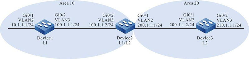
Figure 9–3 Networking of the IS-IS inter-layer leakage
Configuration Steps
Step 1: Configure the IP address of the interfaces. (Omitted)
Step 2: Configure the IS-IS and enable the process on the interface.
#Configure the IS-IS process as 100, area number as 10, and type as Level-1 and enable the process on the interface on Device1.
|
Device1#configure terminal
Device1(config)#router isis 100
Device1(config-isis)#net 10.0000.0000.0001.00
Device1(config-isis)#is-type level-1
Device1(config-isis)#metric-style wide
Device1(config-isis)#exit
Device1(config)#interface vlan2
Device1(config-if-vlan2)#ip router isis 100
Device1(config-if-vlan2)#exit
Device1(config)#interface vlan3
Device1(config-if-vlan3)#ip router isis 100
Device1(config-if-vlan3)#exit
|
#Configure the IS-IS process as 100, area number as 10, and type as Level-1-2 and enable the process on the interface on Device2.
|
Device2#configure terminal
Device2(config)#router isis 100
Device2(config-isis)#net 10.0000.0000.0002.00
Device2(config-isis)#metric-style wide
Device2(config-isis)#exit
Device2(config)#interface vlan2
Device2(config-if-vlan2)#ip router isis 100
Device2(config-if-vlan2)#exit
Device2(config)#interface vlan3
Device2(config-if-vlan3)#ip router isis 100
Device2(config-if-vlan3)#exit
|
#Configure the IS-IS process as 100, area number as 20, and type as Level-2 and enable the process on the interface on Device3.
|
Device3#configure terminal
Device3#configure terminal
Device3(config)#router isis 100
Device3(config-isis)#net 20.0000.0000.0003.00
Device3(config-isis)#is-type level-2
Device3(config-isis)#metric-style wide
Device3(config-isis)#exit
Device3(config)#interface vlan2
Device3(config-if-vlan2)#ip router isis 100
Device3(config-if-vlan2)#exit
Device3(config)#interface vlan3
Device3(config-if-vlan3)#ip router isis 100
Device3(config-if-vlan3)#exit
|
#View the routing information of Device1.
Device1#show ip route
Codes: C - connected, S - static, R - RIP, O - OSPF, OE-OSPF External, M - Management
       D - Redirect, E - IRMP, EX - IRMP external, o - SNSP, B - BGP, i-IS-IS

Gateway of last resort is 100.1.1.2 to network 0.0.0.0

i 0.0.0.0/0 [115/10] via 100.1.1.2, 17:44:09, vlan3
C 10.1.1.0/24 is directly connected, 16:56:18, vlan2
C 100.1.1.0/24 is directly connected, 18:37:57, vlan3
C 127.0.0.0/8 is directly connected, 284:02:13, lo0
i 200.1.1.0/24 [115/20] via 100.1.1.2, 17:44:09, vlan3

Device1#show isis ipv4 route
IS-IS Instance 100, VRF Kernel, IPv4 routes table (Counter 4):
L1 0.0.0.0/0, flags none, metric 10, from learned, installed
     via 100.1.1.2, vlan3, neighbor 0000.0000.0002
L1 10.1.1.0/24, flags none, metric 10, from network connected
     via 0.0.0.0, vlan2
L1 100.1.1.0/24, flags none, metric 10, from network connected
     via 0.0.0.0, vlan3
L1 200.1.1.0/24, flags none, metric 20, from learned, installed
     via 100.1.1.2, vlan3, neighbor 0000.0000.0002

Device1#show isis database detail
IS-IS Instance 100 Level-1 Link State Database (Counter 3, LSP-MTU 1492):
LSPID                  LSP Seq Num  LSP Checksum LSP Holdtime Length ATT/P/OL
0000.0000.0001.00-00*  0x0000007E   0xD5DA         1067       71     0/0/0
  NLPID:    IPv4
  Area Address: 10
  IP Address	100.1.1.1
  Metric: 10        IS-Extended 0000.0000.0001.01
  Metric: 10        IP-Extended 10.1.1.0/24
  Metric: 10        IP-Extended 100.1.1.0/24
0000.0000.0001.01-00*  0x00000073   0xAAAF          471        51    0/0/0
  Metric: 0         IS-Extended 0000.0000.0001.00
  Metric: 0         IS-Extended 0000.0000.0002.00
0000.0000.0002.00-00   0x00000081   0x5926          887        71    1/0/0
  NLPID:    IPv4
  Area Address: 10
  IP Address: 200.1.1.1
  Metric: 10        IS-Extended 0000.0000.0001.01
  Metric: 10        IP-Extended 100.1.1.0/24
  Metric: 10        IP-Extended 200.1.1.0/24
A default routing is in the routing table and the next hop is Device2. No Level-2 routing advertised by Device3 is in the routing table.
#View the routing information of Device2.
Device2#show ip route
Codes: C - connected, S - static, R - RIP, O - OSPF, OE-OSPF External, M Management
       D - Redirect, E - IRMP, EX - IRMP external, o - SNSP, B BGP, i-IS-IS

Gateway of last resort is not set

i 10.1.1.0/24 [115/20] via 100.1.1.1, 16:58:26,vlan3
C 100.1.1.0/24 is directly connected, 18:39:58, vlan3
C 127.0.0.0/8 is directly connected, 20:16:34, lo0
C 200.1.1.0/24 is directly connected, 18:39:37, vlan2
i 210.1.1.0/24 [115/20] via 200.1.1.2, 16:57:56, vlan2

Device2#show isis ipv4 route
IS-IS Instance 100, VRF Kernel, IPv4 routes table (Counter 4):
L1 10.1.1.0/24, flags none, metric 20, from learned, installed
     via 100.1.1.1, vlan3, neighbor 0000.0000.0001
L1 100.1.1.0/24, flags none, metric 10, from network connected
     via 0.0.0.0, vlan3
L1 200.1.1.0/24, flags none, metric 10, from network connected
     via 0.0.0.0, vlan2
L2 210.1.1.0/24, flags none, metric 20, from learned, installed
     via 200.1.1.2, vlan2, neighbor 0000.0000.0003

Device2#show isis database detail
IS-IS Instance 100 Level-1 Link State Database (Counter 3, LSP-MTU 1492):
LSPID        LSP Seq Num LSP Checksum LSP Holdtime Length ATT/P/OL
0000.0000.0001.00-00 0x0000007E 0xD5DA       507      71   0/0/0
  NLPID:    IPv4
  Area Address: 10
  IP Address: 100.1.1.1
  Metric: 10        IS-Extended 0000.0000.0001.01
  Metric: 10        IP-Extended 10.1.1.0/24
  Metric: 10        IP-Extended 100.1.1.0/24
0000.0000.0001.01-00 0x00000074 0xA8B0       799      51   0/0/0
  Metric: 0         IS-Extended 0000.0000.0001.00
  Metric: 0         IS-Extended 0000.0000.0002.00
0000.0000.0002.00-00* 0x00000082 0x5727       1146     71   1/0/0
  NLPID:    IPv4
  Area Address: 10
  IP Address	200.1.1.1
  Metric: 10        IS-Extended 0000.0000.0001.01
  Metric: 10        IP-Extended 100.1.1.0/24
  Metric: 10        IP-Extended 200.1.1.0/24

IS-IS Instance 100 Level-2 Link State Database (Counter 3, LSP-MTU 1492):
LSPID        LSP Seq Num LSP Checksum LSP Holdtime Length ATT/P/OL
0000.0000.0002.00-00* 0x00000081 0x84C0       1047     79   0/0/0
  NLPID:    IPv4
  Area Address: 10
  IP Address: 200.1.1.1
  Metric: 10        IS-Extended 0000.0000.0003.01
  Metric: 20        IP-Extended 10.1.1.0/24
  Metric: 10        IP-Extended 100.1.1.0/24
  Metric: 10        IP-Extended 200.1.1.0/24
0000.0000.0003.00-00 0x00000315 0x9DC7       543      71   0/0/0
  NLPID:    IPv4
  Area Address: 20
  IP Address: 210.1.1.1
  Metric: 10        IS-Extended 0000.0000.0003.01
  Metric: 10        IP-Extended 200.1.1.0/24
  Metric: 10        IP-Extended 210.1.1.0/24
0000.0000.0003.01-00 0x00000070 0xBF97       526      51   0/0/0
  Metric: 0         IS-Extended 0000.0000.0002.00
  Metric: 0         IS-Extended 0000.0000.0003.00
Device2 contains the Level-1 and Level-2 routing.
#View the routing information of Device3 and Device3 contains the Level-1 routing advertised by Device1.
Device3#show ip route
Codes: C - connected, S - static, R - RIP, O - OSPF, OE-OSPF External, M Management
       D - Redirect, E - IRMP, EX - IRMP external, o - SNSP, B BGP, i-IS-IS

Gateway of last resort is not set

i 10.1.1.0/24 [115/30] via 200.1.1.1, 16:59:29, vlan2
i 100.1.1.0/24 [115/20] via 200.1.1.1, 17:47:29, vlan2
C 127.0.0.0/8 is directly connected, 945:29:12, lo0
C 200.1.1.0/24 is directly connected, 18:40:27, vlan2
C 210.1.1.0/24 is directly connected, 16:59:04, vlan3

Device3#show isis ipv4 route
IS-IS Instance 100, VRF Kernel, IPv4 routes table (Counter 4):
L2 10.1.1.0/24, flags none, metric 30, from learned, installed
     via 200.1.1.1, vlan2, neighbor 0000.0000.0002
L2 100.1.1.0/24, flags none, metric 20, from learned, installed
     via 200.1.1.1, vlan2, neighbor 0000.0000.0002
L2 200.1.1.0/24, flags none, metric 10, from network connected
     via 0.0.0.0, vlan2
L2 210.1.1.0/24, flags none, metric 10, from network connected
     via 0.0.0.0, vlan3

Device3#show isis database detail
IS-IS Instance 100 Level-2 Link State Database (Counter 3, LSP-MTU 1492):
LSPID        LSP Seq Num LSP Checksum LSP Holdtime Length ATT/P/OL
0000.0000.0002.00-00 0x00000081 0x84C0       880      79   0/0/0
  NLPID:    IPv4
  Area Address: 10
  IP Address: 200.1.1.1
  Metric: 10        IS-Extended 0000.0000.0003.01
  Metric: 20        IP-Extended 10.1.1.0/24
  Metric: 10        IP-Extended 100.1.1.0/24
  Metric: 10        IP-Extended 200.1.1.0/24
0000.0000.0003.00-00* 0x00000316 0x9BC8       1197     71   0/0/0
  NLPID:    IPv4
  Area Address: 20
  IP Address	210.1.1.1
  Metric: 10        IS-Extended 0000.0000.0003.01
  Metric: 10        IP-Extended 200.1.1.0/24
  Metric: 10        IP-Extended 210.1.1.0/24
0000.0000.0003.01-00* 0x00000070 0xBF97       359      51   0/0/0
  Metric: 0         IS-Extended 0000.0000.0002.00
  Metric: 0         IS-Extended 0000.0000.0003.00
Step 3: Configure the inter-layer leakage.
#Configure the inter-layer leakage for Device2.
|
Device2(config)#router isis 100
Device2(config-isis)#address-family ipv4 unicast
Device2(config-isis-af)#propagate level-2 into level-1
Device2(config-isis-af)#exit
Device2(config-isis)#exit
|
Step 4: Check the result.
#View the routing information of Device1.
Device1#show ip route
Codes: C - connected, S - static, R - RIP, O - OSPF, OE-OSPF External, M - Management
       D - Redirect, E - IRMP, EX - IRMP external, o - SNSP, B - BGP, i-IS-IS

Gateway of last resort is 100.1.1.2 to network 0.0.0.0

i 0.0.0.0/0 [115/10] via 100.1.1.2, 17:44:09, vlan3
C 10.1.1.0/24 is directly connected, 16:56:18, vlan2
C 100.1.1.0/24 is directly connected, 18:37:57, vlan3
C 127.0.0.0/8 is directly connected, 284:02:13, lo0
i 200.1.1.0/24 [115/20] via 100.1.1.2, 17:44:09, vlan3
i 210.1.1.0/24 [115/30] via 100.1.1.2, 00:00:01, vlan3

Device1#show isis ipv4 route
L1 0.0.0.0/0, flags none, metric 10, from learned, installed
     via 100.1.1.2, vlan3, neighbor 0000.0000.0002
L1 100.1.1.0/24, flags none, metric 10, from network connected
     via 0.0.0.0, vlan3
L1 200.1.1.0/24, flags none, metric 20, from learned, installed
     via 100.1.1.2,vlan3, neighbor 0000.0000.0002
L1 210.1.1.0/24, flags inter-area, metric 30, from learned, installed
     via 100.1.1.2, vlan3, neighbor 0000.0000.0002

Device1#show isis database detail
IS-IS Instance 100 Level-1 Link State Database (Counter 3, LSP-MTU 1492):
LSPID        LSP Seq Num LSP Checksum LSP Holdtime Length ATT/P/OL
0000.0000.0001.00-00* 0x0000007F   0xD3DB       668      71   0/0/0
  NLPID:    IPv4
  Area Address: 10
  IP Address: 100.1.1.1
  Metric: 10        IS-Extended 0000.0000.0001.01
  Metric: 10        IP-Extended 10.1.1.0/24
  Metric: 10        IP-Extended 100.1.1.0/24
0000.0000.0001.01-00* 0x00000075 0xA6B1       995      51   0/0/0
  Metric: 0         IS-Extended 0000.0000.0001.00
  Metric: 0         IS-Extended 0000.0000.0002.00
0000.0000.0002.00-00 0x00000083 0x4DA6       984      79   1/0/0
  NLPID:    IPv4
  Area Address: 10
  IP Address: 200.1.1.1
  Metric: 10        IS-Extended 0000.0000.0001.01
  Metric: 10        IP-Extended 100.1.1.0/24
  Metric: 10        IP-Extended 200.1.1.0/24
  Metric: 20        IP-Extended ia 210.1.1.0/24
Besides the default routing, Device1 also learns the Level-2 routing advertised by Device3.
 Switch


