Configure MVR Example
Network Requirements
- Device1 configures the multicast route protocol.
- There are three VLANs in the whole network, vlan2 - vlan4. The port connecting the PC joins the corresponding VLAN in hybrid mode.
- Device2 enables IGMP snooping and configures MVP.
- Multicast Server sends multicast service packets; PC1, PC2 and PC3 can correctly receive the multicast service packets.
Network Topology
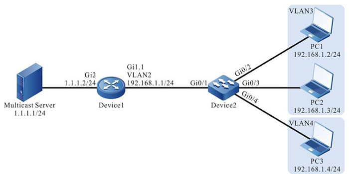
Figure 3-2 MVR typical configuration networking
Configuration Steps
Step 1: Device1 configures the interface IP address and enables the multicast route protocol. (omitted)
Step 2: Configure Device2.
#Create VLAN2-VLAN4 on Device2.
|
Device2#configure terminal
Device2(config)#vlan 2-4
|
#Configure the link type of port gigabitethernet0/1 on Device2 as Trunk, permitting the services of VLAN2 to pass; PVID is configured as 1.
|
Device2(config)#interface gigabitethernet 0/1
Device2(config-if-gigabitethernet0/1)#switchport mode hybrid
Device2(config-if-gigabitethernet0/1)#switchport hybrid tagged vlan 2
Device2(config-if-gigabitethernet0/1)# switchport trunk pvid vlan 1
Device2(config-if-gigabitethernet0/1)#exit
|
#Configure the link type of port gigabitethernet0/2-gigabitethernet0/3 on Device2 as Hybrid, permitting the services of VLAN2-VLAN3 to pass; PVID is configured as 3.
|
Device2(config)#interface gigabitethernet 0/2-0/3
Device2(config-if-range)#switchport mode hybrid
Device2(config-if-range)#switchport hybrid untagged vlan 2-3
Device2(config-if-range)#switchport hybrid pvid vlan 3
Device2(config-if-range)#exit
|
#Configure the link type of port gigabitethernet0/4 on Device2 as Hybrid, permitting the services of VLAN2 and VLAN4 to pass; PVID is configured as 4.
|
Device2(config)#interface gigabitethernet 0/4
Device2(config-if-gigabitethernet0/4)#switchport mode hybrid
Device2(config-if-gigabitethernet0/4)#switchport hybrid untagged vlan 4
Device2(config-if-gigabitethernet0/4)#switchport hybrid untagged vlan 2
Device2(config-if-gigabitethernet0/4)#switchport hybrid pvid vlan 4
Device2(config-if-gigabitethernet0/4)#exit
|
#Configure IGMP snooping.
|
Device2(config)#ip igmp snooping
Device2(config)#ip igmp snooping vlan 2
Device2(config)#ip igmp snooping vlan 3
Device2(config)#ip igmp snooping vlan 4
|
#Configure MVR.
|
Device2(config)#mvr vlan 2
Device2(config)#mvr enable
Device2(config)#exit
|
Step 3: Check the result.
#Query the MVR information.
Device2#show mvr
 MVR status:enable
 multicast-vlan: 2
#PC1, PC2, and PC3 send the IGMPv2 member relation report to add to multicast group 224.1.1.1.
#View the multicast member table of Device2.
Device2#show ip igmp snooping groups
IGMP Snooping Group Membership
Total 3 groups

VLAN ID Interface Name Group Address Expires    Last Reporter  V1 Expires V2 Expires Uptime
---------------------------------------------------------------------------------------------
2       gi0/2          224.1.1.1     00:04:14   192.168.1.2    stopped               00:00:07
2       gi0/3          224.1.1.1     00:04:14   192.168.1.3    stopped               00:00:07
2       gi0/4          224.1.1.1     00:04:14   192.168.1.4    stopped               00:00:07
#Multicast Server sends the multicast service packet with destination address 224.1.1.1. PC1, PC2 and PC3 can correctly receive the multicast service packet.
 Switch


