Network Requirements
- Device1 and Device2 form the stacking system and serve as MVST management device, and Device 3, Device 4 and Device 5 are used as extended cards, and the last two ports of the extended card are connected to the MVST management device;
- Configure Device3 as a template switch and its configuration serves as a public template configuration. When Device4 and Device5 are connected to the MVST domain, automatically deliver the configuration template;
- Change the configuration of Devce3, collect it as the public configuration template, and force it to be distributed to Device4 and Device5.
Network Topology
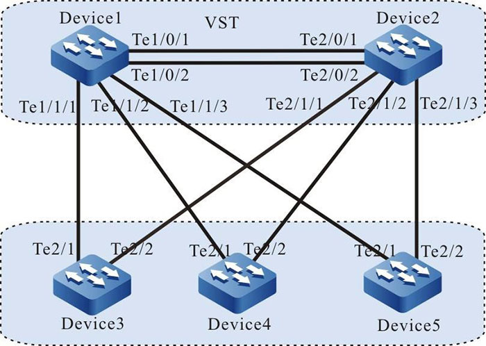
Figure 3-3 Configure the auto delivering of the public template
Configuration Steps
Step 1: Configure the VST system.
#On Device1, configure the No. of the virtual switch member device as 1, and the domain No. as 10, and the priority as 255.
|
Device1#configure terminal
Device1(config)#switch virtual member 1
Do you want to modify member id(Yes|No)?y
% Member ID 1 config will take effect only after the exec command 'switch mode virtual' is issued
Device1(config-vst-member-1)#domain 10
% Domain ID 10 config will take effect only after the exec command 'switch mode virtual' is issued
Device1(config-vst-member-1)#priority 255
Device1(config-vst-member-1)#exit
|
#On Device1, create virtual switch link interface 1, and add ports tentengigabitethernet0/1 and tentengigabitethernet0/2 to virtual switch link interface 1.
|
Device1(config)#vsl-channel 1
Device1(config-vsl-channel-1)#exit
Device1(config)#interface tentengigabitethernet 0/1
Device1(config-if-tentengigabitethernet0/1)#vsl-channel 1 mode on
Device1(config-if-tentengigabitethernet0/1)#exit
Device1(config)#interface tentengigabitethernet 0/2
Device1(config-if-tentengigabitethernet0/2)#vsl-channel 1 mode on
Device1(config-if-tentengigabitethernet0/2)#exit
|
#On Device1, save the configuration.
|
Device1#write
Are you sure to overwrite /flash/startup (Yes|No)?y
Building Configuration...done
Write to startup file.. OK
Write to mode file.. OK
|
#On Device2, configure the No. of the virtual switch member device as 2, the domain No. as 10, and the priority as 200.
|
Device2#configure terminal
Device2(config)#switch virtual member 2
Do you want to modify member id(Yes|No)?y
% Member ID 2 config will take effect only after the exec command 'switch mode virtual' is issued
Device2(config-vst-member-2)#domain 10
% Domain ID 10 config will take effect only after the exec command 'switch mode virtual' is issued
Device2(config-vst-member-2)#priority 200
Device2(config-vst-member-2)#exit
|
#On Device2, create virtual switch link interface 1, and add port tentengigabitethernet1/1 to virtual switch link interface 1.
|
Device2(config)#vsl-channel 1
Device2(config-vsl-channel-1)#exit
Device2(config)#interface tentengigabitethernet 0/1
Device2(config-if-tentengigabitethernet0/1)#vsl-channel 1 mode on
Device2(config-if-tentengigabitethernet0/1)#exit
Device2(config)#interface tentengigabitethernet 0/2
Device2(config-if-tentengigabitethernet0/2)#vsl-channel 1 mode on
Device2(config-if-tentengigabitethernet0/2)#exit
|
#On Device2, save the configuration.
|
Device2#write
Are you sure to overwrite /flash/startup (Yes|No)?y
Building Configuration...done
Write to startup file.. OK
Write to mode file.. OK
|
#Configure the running mode of Device1 as the stacking mode.
|
Device1#switch mode virtual
This command will convert all interface names to naming convention "interface-type member-number/slot/interface",
Please make sure to save current configuration.Do you want to proceed? (yes|no)?y
Converting interface names Building configuration..
Copying the startup configuration to backup file named "startup-backupalone"..
Please wait system reloading is in progress!
ok
Reset system!
%SYS-5-RELOAD: Reload requested
|
#Configure the running mode of Device2 as the stacking mode.
|
Device2#switch mode virtual
This command will convert all interface names to naming convention "interface-type member-number/slot/interface",
Please make sure to save current configuration.Do you want to proceed? (yes|no)?y
Converting interface names Building configuration..
Copying the startup configuration to backup file named "startup-backupalone"..
Please wait system reloading is in progress!
ok
Reset system!
%SYS-5-RELOAD: Reload requested
|
#View on Device1, the stacking system is formed, and Device1 is the master device of the stacking system.
Device1#show switch virtual
Codes: L - local-device,I isolate-device

Virtual Switch Mode        : VIRTUAL
Virtual Switch DomainId    : 10
Virtual Switch mac-address : 0001.7a6a.0255

------------VST MEMBER INFORMATION-------------------------------
CODE MemberID Role    Pri   LocalVsl         RemoteVsl
-----------------------------------------------------------------
L    1        Master  255   vsl-channel 1/1  vsl-channel 2/1
     2        Member  200   vsl-channel 2/1  vsl-channel 1/1
Step 2: Configure the MVST basic functions.
#Configure the stacking system as the MVST management device.
|
Device1(config)#mvst enable
%MVST-NOTIFY-5: MVST is enabled !
Device1(config)#mvst master
Device1(config)#mvst domain-name test
|
#Configure the link aggregation of the stacking system, and enable the MVST detection.
|
Device1(config)#mvst link-aggregation 1 mode lacp
Device1(config)# mvst interface tengigabitethernet 1/1/1,2/1/1 join link-aggregation 1 active
Device1(config)#interface link-aggregation 1
Device1(config-link-aggregation1)#mvst inspection
Device1(config-link-aggregation1)#exit
Device1(config)#mvst link-aggregation 2 mode lacp
Device1(config)# mvst interface tengigabitethernet 1/1/2,2/1/2 join link-aggregation 2 active
Device1(config)#interface link-aggregation 2
Device1(config-link-aggregation2)#mvst inspection
Device1(config-link-aggregation2)#exit
Device1(config)#mvst link-aggregation 3 mode lacp
Device1(config)# mvst interface tengigabitethernet 1/1/3,2/1/3 join link-aggregation 3 active
Device1(config)#interface link-aggregation 3
Device1(config-link-aggregation3)#mvst inspection
Device1(config-link-aggregation3)#exit
|
#On Device3, enable the MVST function.
|
Device3#configure terminal
Device3(config)#mvst enable
%MVST-NOTIFY-5: interface tengigabitethernet2/1 and interface tengigabitethernet2/2 join link-aggregation 1 successfully.
%MVST-NOTIFY-5: MVST is enabled !
|
#On Device4, enable the MVST function.
|
Device4#configure terminal
Device4(config)#mvst enable
%MVST-NOTIFY-5: interface tengigabitethernet2/1 and interface tengigabitethernet2/2 join link-aggregation 1 successfully.
%MVST-NOTIFY-5: MVST is enabled !
|
#On device5, enable the MVST function. Device5#configure terminal Device5(config)#mvst enable
|
Device5#configure terminal
Device5(config)#mvst enable
%MVST-NOTIFY-5: interface tengigabitethernet2/1 and interface tengigabitethernet2/2 join link-aggregation 1 successfully.
%MVST-NOTIFY-5: MVST is enabled !
|
#Add Device3 to MVST domain as an extended card. Check the MVST results on Device1 after the device is added.
#Check the MVST results on Device1. You can see that Device3 joins the MVST domain in the form of an extended card. Its slot is Slave-slot0, and its host name changes to switch-ss0.
Device1#show mvst topo information
-------------------------------------------------------------------------------------------------
role       domain-name   interface           mac             device-type               host-name
-------------------------------------------------------------------------------------------------
Slave-slot test          link-aggregation 1	 0001.7a63.bd76  MyPower S4230-52TXF (V1)  switch-ss0
Master     test	                             0001.7a6a.0258  MyPower S4230-52TXF (V1)  Device1
Step 3: Take Device3 as the template switch, and collect the public configuration template.
#Configure Device3.
|
Device1(config)#configure slave-slot 0
switch-ss0(config)#snmp-server host 1.1.1.1
switch-ss0(config)#snmp-server start
%SNMP-WARMSTART-5 SNMP agent on host switch-ss0 is undergoing a warm start
switch-ss0(config)#snmp-server enable traps vlan
switch-ss0(config)#link-aggregation 1
switch-ss0(config-link-aggregation1)#description management link
switch-ss0(config-link-aggregation1)#exit
switch-ss0(config)#vlan 100,200,300
|
#On Device1, check the configuration of the extended card Device3.
|
Device1#show running-config slave-slot 0
hostname switch-ss0
vlan 100,200,300
link-aggregation 1
description management link
no spanning-tree enable
mvst inspection
exit
snmp-server start
snmp-server view default 1.2 include
snmp-server view default 1.0.8802 include
snmp-server view default 1.1.2 include
snmp-server view default 1.3.111 include
snmp-server view default 1.3.6.1 include
snmp-server community public view default ro
snmp-server enable traps vlan
snmp-server host 1.1.1.1 traps community public version 2
|
#On Device1, save the configuration of Device3.
|
Device1#write slave-slot 0
Are you sure to overwrite slave slot 0 /flash/startup (Yes|No)?y
Device1#
Jan 9 2015 16:32:34: %MVST-WRITE_RESULT-5: The slave slot 0 write to startup file successfully.
|
Step 4: Take the configuration of Device3 as the public configuration template to deliver automatically.
#On Device1, configure the public configuration to deliver automatically.
|
Device1(config)#mvst configure template slave-slot 0
Are you sure to overwrite configure template /flash/mvst-template (Yes|No)?y
Get the slave slot 0 startup-config...OK
Write to /flash/mvst-template... OK.
Device1(config)#
|
Step 5: Add the extended card to the MVST domain to load the configuration template automatically.
#Connect the extended card Device4 and Device5 to the MVST domain, and you can see the print information of automatically delivering the configuration template on Device1.
|
Device1#
%MVST-Slave_slot_add-5:Slave slot 1 add to the MVST
%MVST-Slave_slot_add-5:Slave slot 2 add to the MVST.
%MVST-EXECUTE_COFNIG-5:Slave slot 1 is going to execute configure template /flash/mvst-template.
%MVST-EXECUTE_COFNIG-5:Slave slot 1 execute configure file successfully!
%MVST-EXECUTE_COFNIG-5:Slave slot 2 is going to execute configure template /flash/mvst-template.
%MVST-EXECUTE_COFNIG-5:Slave slot 2 execute configure file successfully!
|
#On Device1, check the MVST result, and the host names of Device4 and Device5 are added with the suffix ss1 and ss2, that is, switch-ss1 and switch-ss2.
Device1#show mvst topo information
--------------------------------------------------------------------------------------------------
role       domain-name    interface           mac             device-type              host-name
--------------------------------------------------------------------------------------------------
Slave-slot test           link-aggregation 1  0001.7a63.bd76  MyPower S4230-52TXF (V1) switch-ss0
Slave-slot test           link-aggregation 2  0001.7a64.72aa  MyPower S4230-52TXF (V1) switch-ss1
Slave-slot test           link-aggregation 3  0001.7a63.bd43  MyPower S4230-52TXF (V1) switch-ss2
Master     test	                              0001.7a6a.0258  MyPower S4230-52TXF (V1) Device1
#On Device1, check the configuration of Device4, and the configuration is delivered successfully.
|
Device1#show running-config slave-slot 1
hostname switch-ss1
vlan 100,200,300
link-aggregation 1
description management link
no spanning-tree enable
mvst inspection
exit
snmp-server start
snmp-server view default 1.2 include
snmp-server view default 1.0.8802 include
snmp-server view default 1.1.2 include
snmp-server view default 1.3.111 include
snmp-server view default 1.3.6.1 include
snmp-server community public view default ro
snmp-server enable traps vlan
snmp-server host 1.1.1.1 traps community public version 2
|
#On Device1, check the configuration of Device5, and the configuration is delivered successfully.
|
Device1#show running-config slave-slot 2
hostname switch-ss2
vlan 100,200,300
link-aggregation 1
description management link
no spanning-tree enable
mvst inspection
exit
snmp-server start
snmp-server view default 1.2 include
snmp-server view default 1.0.8802 include
snmp-server view default 1.1.2 include
snmp-server view default 1.3.111 include
snmp-server view default 1.3.6.1 include
snmp-server community public view default ro
snmp-server enable traps vlan
snmp-server host 1.1.1.1 traps community public version 2
|
Step 6: Force the public configuration template to be delivered.
#Modify the configuration of Device3, and add the ACL configuration.
|
Device1(config)#configure slave-slot 0
switch-ss0(config)#ip access-list extended test
switch-ss0(config-ext-nacl)#permit ip 192.168.0.1 0.0.0.255 any
switch-ss0(config-ext-nacl)#permit ip any any
switch-ss0(config-ext-nacl)#exit
switch-ss0(config)#end
switch-ss0#show access-list
ip access-list extended test
10 permit ip 192.168.0.0 0.0.0.255 any
20 permit ip any any
|
#On Device1, save the configuration of Device3.
|
Device1#write slave-slot 0
Are you sure to overwrite slave slot 0 /flash/startup (Yes|No)?y
Device1#
%MVST-WRITE_RESULT-5: The slave slot 0 write to startup file successfully.
%MVST-COLLECT_STARTUP-5: Collect slave slot 0 startup begin.
%MVST-COLLECT_STARTUP-5: Collect slave slot 0 startup OK.
|
#On Device1, re-collect the startup of Device3 as the new public configuration template.
|
Device1(config)#mvst configure template slave-slot 0
Are you sure to overwrite configure template /flash/mvst-template (Yes|No)?y
Get the slave slot 0 startup-config...OK
Write to /flash/mvst-template... OK.
|
#On Device1, force the public configuration template to be distributed to Device4, and there is the printing information of successful distribution.
|
Device1(config)#mvst apply configure template slave-slot 1
%MVST-EXECUTE_COFNIG-5: Slave slot 1 is going to execute configure template /flash/ mvst-template
%MVST-EXECUTE_COFNIG-5: Slave slot 1 execute configure file successfully!
|
#Check if the configuration of Device4 contains the latest ACL configuration.
|
Device1(config)#configure slave-slot 1
switch-ss1#show access-list
ip access-list extended test
10 permit ip 192.168.0.0 0.0.0.255 any
20 permit ip any any
|
 Switch


