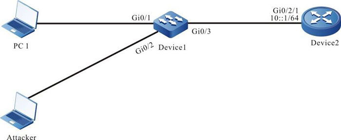
Network Requirements
- Device 1 is connected to gateway Device 2 through gigabitothernet0/3.
- Device 2 enables RA service (enables RA packet sending function).
- Device 1 enables ND snooping function. When an attacker sends illegal NS/NA/ RS/RA packets in the network, Device1 discards these invalid ND packets to ensure the communication between the valid user and the gateway.
Network Topology

Figure 6-1 Networking of configuring ND Snooping basic functions
Configuration Steps
Step 1: On Device1, configure the VLAN and port link type.
#Create VLAN2.
|
Device1#configure terminal
Device1(config)#vlan 2
Device1(config-vlan2)#exit
|
#Configure the link type of port gigabitethernet0/1-gigabitethernet0/3 as Access, permitting the services of VLAN2 to pass.
|
Device1(config)#interface gigabitethernet 0/1-0/3
Device1(config-if-range)#switchport mode access
Device1(config-if-range)#switchport access vlan 2
Device1(config-if-range)#exit
|
Step 2: On L3 interface gigabitethernet0/2/1 of gateway device Device2, configure the IPv6 address.
|
Device2(config)#interface gigabitethernet 0/2/1
Device2 (config-if-gigabitethernet0/2/1)#ipv6 address 10::1/64
Device2 (config-if-gigabitethernet0/2/1)#exit
|
Step 3: On the gateway device Device2, enable the RA service (enable the RA packet sending function).
|
Device2(config)#interface gigabitethernet 0/2/1
Device2 (config-if-gigabitethernet0/2/1)#no ipv6 nd suppress-ra period
Device2 (config-if-gigabitethernet0/2/1)#no ipv6 nd suppress-ra response
Device2 (config-if-gigabitethernet0/2/1)#exit
|
Step 4: On Device1, configure the ND Snooping function.
#Globally enable the ND Snooping function.
|
Device1(config)#nd snooping enable
|
#VLAN2 enables the ND Snooping function.
|
Device1(config)#vlan 2
Device1(config-vlan2)#nd snooping enable
Device1(config-vlan2)#exit
|
#Configure port gigabitethernet0/3 as trust interface.
|
Device1(config)#interface gigabitethernet 0/3
Device1(config-if-gigabitethernet0/3)#nd snooping trusted
Device1(config-if-gigabitethernet0/3)#exit
|
Step 5: Check the result.
#View that Device1 gets the prefix information sent by the gateway device Device2.
Device1#show nd snooping prefix
prefix    length  valid-time   preferred-time
---------------------------------------------
10::      64      2592000      604800
Total number: 1
#After PC1 configure the IPv6 address 10::3 in the management range of the prefix 10::/64, view the ND Snooping entry on Device.
Device1#show nd snooping user-bind dynamic
ipv6-address   mac-address     vlan  interface  type
10::3	       0857.00da.4715  2     gi0/1      dynamic
On Device1, generate the ND Snooping entry of the IP, MAC, VLAN, access port information of PC1.
#Attacker simulates the IP of PC1 to send NS, NA, and RS packets to the gateway. The device receives the NS, NA, RS packets from the attacker, judges that it is inconsistent with the recorded ND snooping entry, discards it, and makes relevant records in the ND snooping statistics information.
Device1#show nd snooping statistics
      Statistics for lpu 0 nd snooping:
      lladdrInvalid:       0
      dadPacketDeal:       0
      nsPacketPass:       0
      nsPacketDrop:       1
      naPacketPass:       0
      naPacketDrop:       1
      rsPacketDrop:       1
      rsPacketPass:       0
      raPacketPass:       0
      raPacketDrop:       0
      rdPacketDrop:       0
      rdPacketPass:       0
      sendDtPktFail:      0
      sendDtPktOk:        0
#Attacker simulates the gateway to send the RA packet to PC1. Device receives the RA packet of Attacker, judges that the RA packet is received from the un-trust packet, drops it, and makes the related records in the ND Snooping statistics information.
Device1#show nd snooping statistics
      Statistics for lpu 0 nd snooping:
      lladdrInvalid:      0
      dadPacketDeal:      0
      nsPacketPass:       0
      nsPacketDrop:       0
      naPacketPass:       0
      naPacketDrop:       0
      rsPacketDrop:       0
      rsPacketPass:       0
      raPacketPass:       0
      raPacketDrop:       1
      rdPacketDrop:       0
      rdPacketPass:       0
      sendDtPktFail:      0
      sendDtPktOk:        0
 Switch
 Wifi - Access Point
 Firewall
 Router
 Module Quang
![Module Quang Cisco]() Module Quang Cisco
Module Quang Cisco![Module quang HPE]() Module quang HPE
Module quang HPE![Module quang Maipu]() Module quang Maipu
Module quang Maipu![Module quang Brocade]() Module quang Brocade
Module quang Brocade![Module quang Fortinet]() Module quang Fortinet
Module quang Fortinet![Module quang Aruba]() Module quang Aruba
Module quang Aruba![Module quang OEM]() Module quang OEM
Module quang OEM![Module quang Juniper]() Module quang Juniper
Module quang Juniper![Module quang Dell]() Module quang Dell
Module quang Dell![Module quang Palo Alto]() Module quang Palo Alto
Module quang Palo Alto![Module quang Huawei]() Module quang Huawei
Module quang Huawei![Module quang Arista]() Module quang Arista
Module quang Arista![Module quang F5]() Module quang F5
Module quang F5![Module quang H3C]() Module quang H3C
Module quang H3C![Module Quang Allied Telesis]() Module Quang Allied Telesis
Module Quang Allied Telesis![Module quang SonicWall]() Module quang SonicWall
Module quang SonicWall![Module quang Mikrotik]() Module quang Mikrotik
Module quang Mikrotik![Module quang Handar]() Module quang Handar
Module quang Handar Máy chủ (Server)
 Thiết bị lưu trữ (SAN, NAS)
 Load Balancing
 Video Conferencing
 Phụ kiện máy chủ
 Thiết Bị IoT
 Phụ Kiện Mạng


.png)


