Network Requirements
- IPv6 Network1 and IPv6 Network2 are the private IPv6 network of Device1 and Device3 respectively.
- PC1 in IPv6 Network1 and PC2 in IPv6 Network2 communicate via the 6to4 tunnel between Device1 and Device3.
Network Topology
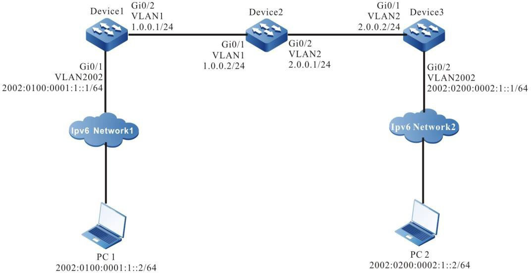
Figure 11-2 Networking for Configuring the basic functions of the 6to4 tunnel
Configuration Steps
Step 1: Configure the IP address of the interface (omitted).
Step 2: Configure OSPF, making Device1, Device2, and Device3 communicate with each other.
#Configure Device1.
|
Device1#configure terminal
Device1(config)#router ospf 100
Device1(config-ospf)#network 1.0.0.0 0.0.0.255 area 0
Device1(config-ospf)#exit
|
#Configure Device2.
|
Device2#configure terminal
Device2(config)#router ospf 100
Device2(config-ospf)#network 1.0.0.0 0.0.0.255 area 0
Device2(config-ospf)#network 2.0.0.0 0.0.0.255 area 0
Device2(config-ospf)#exit
|
#Configure Device3.
|
Device3#configure terminal
Device3(config)#router ospf 100
Device3(config-ospf)#network 2.0.0.0 0.0.0.255 area 0
Device3(config-ospf)#exit
|
#Query the route table of Device3.
Device3#show ip route
Codes: C - connected, S - static, R - RIP, O - OSPF, OE-OSPF External, M - Management
       D - Redirect, E - IRMP, EX - IRMP external, o - SNSP, B - BGP, i-ISIS

Gateway of last resort is not set

O   1.0.0.0/24 [110/65536] via 2.0.0.1, 00:18:40, vlan2
C 2.0.0.0/24 is directly connected, 00:22:27, vlan2

-
The querying methods of Device1 and Device2 are the same as that of Device3, so the querying process is omitted.
Step 3: Configure serviceloop-group.
#On Device1, create serviceloop-group, and then add route-port to serviceloop-group.
|
Device1(config)#erviceloop-group 1
Device1(config)#interface gigabitethernet0/5
Device1(config-if-gigabitethernet0/5)#no switchport
Device1(config-if-gigabitethernet0/5)#serviceloop-group 1 active
If the serviceloop-group is used to tunnel, Please make sure the interface switch to routed-port,
This command will clear all config in the interface, Please make sure the interface in default state. Do you want to proceed? (yes|no)?yes
Device1(config-if-gigabitethernet0/5)#exit
|
#On Device3, create serviceloop-group, and add route-port to serviceloop-group.
|
Device1(config)#erviceloop-group 1
Device1(config)#interface gigabitethernet0/5
Device1(config-if-gigabitethernet0/5)#no switchport
Device1(config-if-gigabitethernet0/5)#serviceloop-group 1 active
If the serviceloop-group is used to tunnel, Please make sure the interface switch to routed-port,
This command will clear all config in the interface, Please make sure the interface in default state. Do you want to proceed? (yes|no)?yes
Device1(config-if-gigabitethernet0/5)#exit
|
Step 4: Configure the 6to4 tunnel.
#On Device1, configure the 6to4 tunnel (tunnel1), the source address is 1.0.0.1, serviceloop-group is 1, and the IPv6 address is 2002:100:1::1.
|
Device1(config)#interface tunnel 1
Device1(config-if-tunnel1)#tunnel mode ipv6ip 6to4
Device1(config-if-tunnel1)#tunnel service-loop 1
Device1(config-if-tunnel1)#tunnel source 1.0.0.1
Device1(config-if-tunnel1)#ipv6 address 2002:100:1::1/64
Device1(config-if-tunnel1)#exit
|
#On Device3, configure the 6to4 tunnel (tunnel1), the source address is 2.0.0.2, serviceloop-group is 1, and the IPv6 address is 2002:200:2::1.
|
Device3(config)#interface tunnel 1
Device3(config-if-tunnel1)#tunnel mode ipv6ip 6to4
Device1(config-if-tunnel1)#tunnel service-loop 1
Device3(config-if-tunnel1)#tunnel source 2.0.0.2
Device3(config-if-tunnel1)#ipv6 address 2002:200:2::1/64
Device3(config-if-tunnel1)#exit
|
#Query the 6to4 tunnel information of Device3.
Device3# show tunnel 1
Tunnel 1:
    Tunnel mode is ipv6ip 6to4
    Source ipv4 address is 2.0.0.2(Source ipv4 address is up on source interface vlan2)
    Tunnel state is up
    Encapsulation vrf is global(0x0)
    TTL(time-to-live) is 255
    TOS(type of service) is not set total(1)
- The querying method of Device1is the same as that of Device3, so the querying process is omitted.
- When the tunnel is not in the same network segment, it is necessary to configure the static routing to the peer tunnel on the devices at both ends of the tunnel, and the output interface is the tunnel interface.
Step 5: Configure the static route.
#On Device1, configure the static route to the segment 2002::/16 with the egress interface (tunnel1).
|
Device1(config)#ipv6 route 2002::/16 tunnel1
|
#On Device3, configure the static route to the segment 2002::/16 with the egress interface (tunnel1).
|
Device3(config)#ipv6 route 2002::/16 tunnel1
|
#Query the IPv6 route table of Device3.
Device3#show ipv6 route
Codes: C - Connected, L - Local, S - static, R - RIP, B - BGP, i-ISIS
       U - Per-user Static route
       O - OSPF, OE-OSPF External, M - Management

L ::1/128 [0/0]
     via ::, 6w1d:02:11:13, lo0
S 2002::/16 [1/100000]
     via ::, 00:10:31, tunnel1
C 2002:200:2::/64 [0/0]
     via ::, 00:12:51, tunnel1
L 2002:200:2::1/128 [0/0]
     via ::, 00:12:49, lo0
C 2002:200:2:1::/64 [0/0]
     via ::, 00:12:15, vlan2002
L 2002:200:2:1::1/128 [0/0]
     via ::, 00:12:13, lo0
-
The querying method of Device1is the same as that of Device3, so the querying process is omitted.
Step 6: Check the result.
#On PC1, ping the PC2 address 2002:200:2:1::2.
C:\>ping6 2002:200:2:1::2 –s 2002:0100:0001:1::2

Pinging 2002:200:2:1::2 with 32 bytes of data:

Reply from 2002:200:2:1::2: time<1ms
Reply from 2002:200:2:1::2: time<1ms
Reply from 2002:200:2:1::2: time<1ms
Reply from 2002:200:2:1::2: time<1ms

Ping statistics for 2002:200:2:1::2:
    Packets: Sent = 4, Received = 4, Lost = 0 (0% loss), Approximate round trip times in milli-seconds:
    Minimum = 0ms, Maximum = 0ms, Average = 0ms
#PC1 can ping PC2 address 2002:200:2:1::2.
 Switch


