Network Requirements
- On Device1 and Device2 interface, enable VRRP and add to the link group. Only the Active group in the link group interacts the protocol packets.
- The VRRP status of the non-Active keeps consistent with the VRRP status of the Active group. When the Active group status switches, the non-Active group also switches.
Network Topology
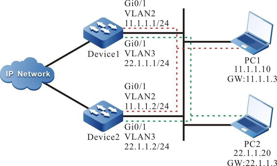
Figure 5-4 VRRP multi-backup group networking
Configuration Steps
Step 1: Configure VLAN and add the port to the corresponding VLAN.(Omitted)
Step 2: Configure the IP address of the interface.(Omitted)
Step 3: Create one VRRP link group.
#Configure VRRP link group 1 on Device1.
|
Device1#configure terminal
Device1(config)#vrrp linkgroup 1
|
#Configure VRRP link group 1 on Device2.
|
Device2#configure terminal
Device2(config)#vrrp linkgroup 1
|
Step 4: Create the VRRP group.
#Configure the virtual IP address of the VRRP group 1 as 11.1.1.3 on Device1 interface.
|
Device1(config)#interface vlan 2
Device1(config-if-vlan2)#vrrp 1 ip 11.1.1.3
Device1(config-if-vlan2)#exit
|
#Configure the virtual IP address of the VRRP group 2 as 22.1.1.3 on Device1 interface.
|
Device1(config)#interface vlan 3
Device1(config-if-vlan3)#vrrp 2 ip 22.1.1.3
Device1(config-if-vlan3)#exit
|
#Configure the virtual IP address of the VRRP group 1 as 11.1.1.3 on Device2 interface.
|
Device2(config)#interface vlan 2
Device2(config-if-vlan2)#vrrp 1 ip 11.1.1.3
Device2(config-if-vlan2)#exit
|
#Configure the virtual IP address of the VRRP group 2 as 22.1.1.3 on Device2 interface.
|
Device2(config)#interface vlan 3
Device2(config-if-vlan3)#vrrp 2 ip 22.1.1.3
Device2(config-if-vlan3)#exit
|
Step 5: Configure VRRP to add to the link group.
#On Device1, the VRRP group 1 is added to the link group in Active mode.
|
Device1(config)#interface vlan 2
Device1(config-if-vlan2)#vrrp 1 linkgroup 1 active
Device1(config-if-vlan2)#exit
|
#On Device1, the VRRP group 2 is added to the link group in non-Active mode.
|
Device1(config)#interface vlan 3
Device1(config-if-vlan3)#vrrp 2 linkgroup 1
Device1(config-if-vlan3)#exit
|
#On Device2, the VRRP group 1 is added to the link group in Active mode.
|
Device2(config)#interface vlan 2
Device2(config-if-vlan2)#vrrp 1 linkgroup 1 active
Device2(config-if-vlan2)#exit
|
#On Device2, the VRRP group 2 is added to the link group in non-Active mode.
|
Device2(config)#interface vlan 3
Device2(config-if-vlan3)#vrrp 2 linkgroup 1
Device2(config-if-vlan3)#exit
|
Step 6: Check the result.
#View the VRRP status on Device1.
Device1#show vrrp
Interface vlan2 (Flags 0x1)
  Pri-addr : 11.1.1.1
  Vrf : 0
  Virtual router : 1
    Linkgroup : 1
    Active : TRUE
    Virtual IP address : 11.1.1.3
    Virtual MAC address : 00-00-5e-00-01-01
    Depend prefix: 11.1.1.1/24
    State : Backup
    Master addr : 11.1.1.2
    Normal priority : 100
    Currnet priority : 100
    Priority reduced : 0
    Preempt-mode : YES
    Advertise-interval : 1
    Authentication Mode : None

Interface vlan3 (Flags 0x1)
  Pri-addr : 22.1.1.1
  Vrf : 0
  Virtual router : 2
    Linkgroup : 1
    Active : FALSE
    Virtual IP address : 22.1.1.3
    Virtual MAC address : 00-00-5e-00-01-02
    Depend prefix:22.1.1.1/24
    State : Backup
    Master addr : 0.0.0.0
    Normal priority : 100
    Currnet priority : 100
    Priority reduced : 0
    Preempt-mode : YES
    Advertise-interval : 1 Authentication Mode : None
#View the VRRP status on Device2.
Device2#show vrrp
Interface vlan2 (Flags 0x1)
  Pri-addr : 11.1.1.2
  Vrf : 0
  Virtual router : 1
    Linkgroup : 1
    Active : TRUE
    Virtual IP address : 11.1.1.3
    Virtual MAC address : 00-00-5e-00-01-01 , installed into HW
    Depend prefix:11.1.1.2/24
    State : Master
    Normal priority : 100
    Currnet priority : 100
    Priority reduced : 0
    Preempt-mode : YES
    Advertise-interval : 1
    Authentication Mode : None

Interface vlan3 (Flags 0x1)
  Pri-addr : 22.1.1.2
  Vrf : 0
  Virtual router : 2
    Linkgroup : 1
    Active : FALSE
    Virtual IP address : 22.1.1.3
    Virtual MAC address : 00-00-5e-00-01-02 , installed into HW
    Depend prefix:22.1.1.2/24
    State : Master
    Normal priority : 100
    Currnet priority : 100
    Priority reduced : 0
    Preempt-mode : YES
    Advertise-interval : 1 Authentication Mode : None
We can see that the VRRP status of the non-Active group and Active group keep consistent.
Step 7: Configure the priority of VLAN2 interface in Device1 as 110, making the status change.
|
Device1(config)#interface vlan 2
Device1(config-if-vlan2)#vrrp 1 priority 110
Device1(config-if-vlan2)#exit
|
#View the VRRP status on Device1.
Device1#show vrrp
Interface vlan2 (Flags 0x1)
  Pri-addr : 11.1.1.1
  Vrf : 0
  Virtual router : 1
    Linkgroup : 1
    Active : TRUE
    Virtual IP address : 11.1.1.3
    Virtual MAC address : 00-00-5e-00-01-01 , installed into HW
    Depend prefix:11.1.1.1/24
    State : Master
    Normal priority : 110
    Currnet priority : 110
    Priority reduced : 0
    Preempt-mode : YES
    Advertise-interval : 1
    Authentication Mode : None

Interface vlan3 (Flags 0x1)
  Pri-addr : 22.1.1.1
  Vrf : 0
  Virtual router : 2
    Linkgroup : 1
    Active : FALSE
    Virtual IP address : 22.1.1.3
    Virtual MAC address : 00-00-5e-00-01-02 , installed into HW
    Depend prefix:22.1.1.1/24
    State : Master
    Normal priority : 100
    Currnet priority : 100
    Priority reduced : 0
    Preempt-mode : YES
    Advertise-interval : 1
    Authentication Mode : None
#View the VRRP status on Device2.
Device2#show vrrp
Interface vlan2 (Flags 0x1)
  Pri-addr : 11.1.1.2
  Vrf : 0
  Virtual router : 1
    Linkgroup : 1
    Active : TRUE
    Virtual IP address : 11.1.1.3
    Virtual MAC address : 00-00-5e-00-01-01
    Depend prefix:11.1.1.2/24
    State : Backup
    Master addr : 11.1.1.1
    Normal priority : 100
    Currnet priority : 100
    Priority reduced : 0
    Preempt-mode : YES
    Advertise-interval : 1
    Authentication Mode : None

Interface vlan3 (Flags 0x1)
  Pri-addr : 22.1.1.2
  Vrf : 0
  Virtual router : 2
    Linkgroup : 1
    Active : FALSE
    Virtual IP address : 22.1.1.3
    Virtual MAC address : 00-00-5e-00-01-02
    Depend prefix:22.1.1.2/24
    State : Backup
    Master addr : 0.0.0.0
    Normal priority : 100
    Currnet priority : 100
    Priority reduced : 0
    Preempt-mode : YES
    Advertise-interval : 1
    Authentication Mode : None
We can see that when the status of the Active group switches, the non-Active group also changes and keeps consistent with the Active group. The Active group in the link group is responsible for sending the protocol packets, but the non-Active group does not send packets. This can reduce the interacting of the protocol packets and the network load.

-
The sending interval granularity can be smaller. The minimum can be configured to the ms level, so as to reach the fast switching.
 Switch


