Network Requirements
- Run IGP protocol ISPF and set up IBGP neighbors between Device1 and Device2 and between Device1 and Device3, and set up EBGP neighbors between Device4 and Device2 and between Device4 and Device3.
- Configure a routing policy on Device2 and Device3 so that the data of Device1 reaches network segment 100.1.1.0/24 through Device2, reaches network segment 110.1.1.0/24 through Device3, reaches network segment 120.1.1.0/24 through Device2, and reaches network segment 130.1.1.0/24 through Device3.
Network Topology
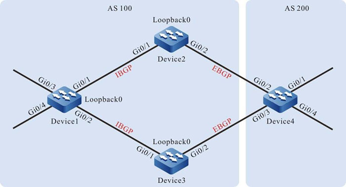
Figure 15–2 Configuring a routing policy for BGP
|
Device
|
Interface
|
VLAN
|
IP Address
|
|
Device1
|
Gi0/1
|
2
|
1.0.0.1/24
|
|
Gi0/2
|
3
|
2.0.0.1/24
|
|
Gi0/3
|
4
|
120.1.1.1/24
|
|
Gi0/4
|
5
|
130.1.1.1/24
|
|
Loopback0
|
|
38.1.1.1/32
|
|
Device2
|
Gi0/1
|
2
|
1.0.0.2/24
|
|
Gi0/2
|
3
|
3.0.0.1/24
|
|
Loopback0
|
|
39.1.1.1/32
|
|
Device3
|
Gi0/1
|
2
|
2.0.0.2/24
|
|
Gi0/2
|
3
|
4.0.0.1/24
|
|
Loopback0
|
|
40.1.1.1/32
|
|
Device
|
Interface
|
VLAN
|
IP Address
|
|
Device4
|
Gi0/1
|
2
|
100.1.1.1/24
|
|
Gi0/2
|
3
|
3.0.0.2/24
|
|
Gi0/3
|
4
|
4.0.0.2/24
|
|
Gi0/4
|
5
|
110.1.1.1/24
|
Configuration Steps
Step 1: Configure the VLAN and join the interface to the corresponding VLAN. (Omitted)
Step 2: Configure the IP addresses of the interfaces. (Omitted)
Step 3: Configure OSPF so that loopback routes are reachable between devices.
#Configure Device1.
|
Device1#configure terminal
Device1(config)#router ospf 100
Device1(config-ospf)#network 1.0.0.0 0.0.0.255 area 0
Device1(config-ospf)#network 2.0.0.0 0.0.0.255 area 0
Device1(config-ospf)#network 38.1.1.1 0.0.0.0 area 0
Device1(config-ospf)#exit
|
#Configure Device2.
|
Device2#configure terminal
Device2(config)#router ospf 100
Device2(config-ospf)#network 1.0.0.0 0.0.0.255 area 0
Device2(config-ospf)#network 39.1.1.1 0.0.0.0 area 0
Device2(config-ospf)#exit
|
#Configure Device3.
|
Device3#configure terminal
Device3(config)#router ospf 100
Device3(config-ospf)#network 2.0.0.0 0.0.0.255 area 0
Device3(config-ospf)#network 40.1.1.1 0.0.0.0 area 0
Device3(config-ospf)#exit
|
#Query the routing table of Device1.
Device1#show ip route ospf
Codes: C - Connected, L - Local, S - static, R - RIP, B - BGP, i-ISIS
       U - Per-user Static route
       O - OSPF, OE-OSPF External, M - Management, E - IRMP, EX - IRMP external

O 39.1.1.1/32 [110/2] via 1.0.0.2, 19:11:33, vlan2
O 40.1.1.1/32 [110/2] via 2.0.0.2, 18:56:32, vlan3
#Query the routing table of Device2.
Device2#show ip route ospf
Codes: C - Connected, L - Local, S - static, R - RIP, B BGP, i-ISIS
       U Per-user Static route
       O - OSPF, OE-OSPF External, M - Management, E - IRMP, EX IRMP external

O 2.0.0.0/24 [110/2] via 1.0.0.1, 19:19:10, vlan2
O 38.1.1.1/32 [110/2] via 1.0.0.1, 19:09:43, vlan2
O 40.1.1.1/32 [110/3] via 1.0.0.1, 18:56:49, vlan2
#Query the routing table of Device3.
Device3#show ip route ospf
Codes: C - Connected, L - Local, S - static, R - RIP, B BGP, i-ISIS
       U Per-user Static route
       O - OSPF, OE-OSPF External, M - Management, E - IRMP, EX IRMP external

O 1.0.0.0/24 [110/2] via 2.0.0.1, 19:17:33, vlan2
O 38.1.1.1/32 [110/2] via 2.0.0.1, 19:09:59, vlan2
O 39.1.1.1/32 [110/3] via 2.0.0.1, 19:12:06, vlan2
After the configuration is completed, Device1 can set up OSPF neighbors respectively with Device2 and Device3 and the devices can learn the Loopback routes of the peer end.
Step 4: Configure BGP.
#Configure Device1.
Configure Device1 to set up IBGP neighbors respectively with Device2 and Device3 through Loopback interfaces and advertises routes 120.1.1.0/24 and 130.1.1.0/24 to the BGP routing table.
|
Device1(config)#router bgp 100
Device1(config-bgp)#neighbor 39.1.1.1 remote-as 100
Device1(config-bgp)#neighbor 39.1.1.1 update-source loopback0
Device1(config-bgp)#neighbor 40.1.1.1 remote-as 100
Device1(config-bgp)#neighbor 40.1.1.1 update-source loopback0
Device1(config-bgp)#network 120.1.1.0 255.255.255.0
Device1(config-bgp)#network 130.1.1.0 255.255.255.0
Device1(config-bgp)#exit
|
#Configure Device2.
|
Device2(config)#router bgp 100
Device2(config-bgp)#neighbor 38.1.1.1 remote-as 100
Device2(config-bgp)#neighbor 38.1.1.1 update-source loopback0
Device2(config-bgp)#neighbor 38.1.1.1 next-hop-self
Device2(config-bgp)#neighbor 3.0.0.2 remote-as 200
Device2(config-bgp)#exit
|
#Configure Device3.
|
Device3(config)#router bgp 100
Device3(config-bgp)#neighbor 38.1.1.1 remote-as 100
Device3(config-bgp)#neighbor 38.1.1.1 update-source loopback0
Device3(config-bgp)#neighbor 38.1.1.1 next-hop-self
Device3(config-bgp)#neighbor 4.0.0.2 remote-as 200
Device3(config-bgp)#exit
|
#Configure Device4.
Configure Device4 to set up EBGP neighbors respectively with Device2 and Device3 and advertise routes 100.1.1.0/24 and 110.1.1.0/24 to the BGP routing table.
|
Device4#configure terminal
Device4(config)#router bgp 200
Device4(config-bgp)#neighbor 3.0.0.1 remote-as 100
Device4(config-bgp)#neighbor 4.0.0.1 remote-as 100
Device4(config-bgp)#network 100.1.1.0 255.255.255.0
Device4(config-bgp)#network 110.1.1.0 255.255.255.0
Device4(config-bgp)#exit
|
#Query the BGP routing information of Device1.
Device1#show ip bgp
BGP table version is 2, local router ID is 38.1.1.1
Status codes: s suppressed, d damped, h history, * valid, > best, i - internal,
              S Stale
Origin codes: i - IGP, e - EGP, ? - incomplete
           Network          Next Hop     Metric  LocPrf  Weight Path
[B]*>i 100.1.1.0/24	39.1.1.1       0         100      0        200 i
[B]* i                        40.1.1.1       0         100      0        200 i
[B]*>i 110.1.1.0/24   39.1.1.1       0         100      0        200 i
[B]* i                        40.1.1.1       0         100      0         200 i
[B]*> 120.1.1.0/24    0.0.0.0         0                    32768  i
[B]*> 130.1.1.0/24    0.0.0.0         0                    32768  i
#Query the routing table of Device1.
Device1#show ip route bgp
Codes: C - Connected, L - Local, S - static, R - RIP, B BGP, i-ISIS
       U Per-user Static route
       O - OSPF, OE-OSPF External, M - Management, E - IRMP, EX IRMP external

B 100.1.1.0/24 [200/0] via 39.1.1.1, 19:03:19, vlan2
B 110.1.1.0/24 [200/0] via 39.1.1.1, 19:03:19, vlan2
According to the BGP routing table of Device1, data that are targeted at network segments 100.1.1.0/24 and 110.1.1.0/24 have two valid routes respectively. Because the router ID of Device2 is smaller, so the BGP data that are targeted at network segments 100.1.1.0/24 and 110.1.1.0/24 choose to pass Device2 by default.
#Query the BGP routing information of Device4.
Device4#show ip bgp
BGP table version is 3, local router ID is 110.1.1.1
Status codes: s suppressed, d damped, h history, * valid, > best, i internal,
              S Stale
Origin codes: i - IGP, e - EGP, ? incomplete

          Network               Next Hop     Metric LocPrf Weight Path
[B]*> 100.1.1.0/24        0.0.0.0        0                  32768  i
[B]*> 110.1.1.0/24        0.0.0.0        0                  32768  i
[B]*   120.1.1.0/24        4.0.0.1        0                  0         100 i
[B]*>                           3.0.0.1         0                  0         100 i
[B]*   130.1.1.0/24        4.0.0.1         0                 0         100 i
[B]*>                           3.0.0.1         0                 0          100 i
#Query the routing table of Device4.
Device4#show ip route bgp
Codes: C - Connected, L - Local, S - static, R - RIP, B BGP, i-ISIS
       U Per-user Static route
       O - OSPF, OE-OSPF External, M - Management, E - IRMP, EX IRMP external

B 120.1.1.0/24 [20/0] via 3.0.0.1, 19:25:05, vlan3
B 130.1.1.0/24 [20/0] via 3.0.0.1, 19:25:05, vlan3
According to the BGP routing table of Device4, the data that are targeted at network segments 120.1.1.0/24 and 130.1.1.0/24 have two valid routes. Because Device4 first sets up a neighbor relation with Device2, it takes longer time for Device2 to learn the two routes, so BGP data that are targeted at the network segments 120.1.1.0/24 and 130.1.1.0/24 choose to pass Device2 by default.
Step 5: Configure a prefix list and routing policy.
#Configure Device2.
Configure a prefix list to allow routes 100.1.1.0/24 and 130.1.1.0/24 to pass.
|
Device2(config)#ip prefix-list 1 permit 100.1.1.0/24
Device2(config)#ip prefix-list 2 permit 130.1.1.0/24
|
Configure the routing policy lp so that the prefix list 1 of Device2 allows setting local-preference for routes.
|
Device2(config)#route-map lp 10
Device2(config-route-map)#match ip address prefix-list 1
Device2(config-route-map)#set local-preference 200
Device2(config-route-map)#exit
Device2(config)#route-map lp 20
Device2(config-route-map)#exit
|
Configure the routing policy med so that the prefix list 2 of Device2 allows setting the MED property for routes.
|
Device2(config)#route-map med 10
Device2(config-route-map)#match ip address prefix-list 2
Device2(config-route-map)#set metric 10
Device2(config-route-map)#exit
Device2(config)#route-map med 20
Device2(config-route-map)#exit
|
#Configure Device3.
Configure a prefix list to allow routes 110.1.1.0/24 and 120.1.1.0/24 to pass.
|
Device3(config)#ip prefix-list 1 permit 110.1.1.0/24
Device3(config)#ip prefix-list 2 permit 120.1.1.0/24
|
Configure the routing policy lp so that the prefix list 1 of Device3 allows setting local-preference for routes.
|
Device3(config)#route-map lp 10
Device3(config-route-map)#match ip address prefix-list 1
Device3(config-route-map)#set local-preference 200
Device3(config-route-map)#exit
Device3(config)#route-map lp 20
Device3(config-route-map)#exit
|
Configure the routing policy med so that the prefix list 2 of Device3 allows setting the MED property for routes.
|
Device3(config)#route-map med 10
Device3(config-route-map)# match ip address prefix-list 2
Device3(config-route-map)#set metric 10
Device3(config-route-map)#exit
Device3(config)#route-map med 20
Device3(config-route-map)#exit
|

-
In configuring a routing policy, you can create a matching rule based on a prefix list or ACL. The prefix list can precisely match routing masks while the ACL cannot match routing masks.
Step 6: Configure a routing policy for BGP.
#Configure Device2.
Apply the routing policy lp to the outgoing routes of neighbor 38.1.1.1 and apply the routing policy med to the outgoing routes of neighbor 3.0.0.2.
|
Device2(config)#router bgp 100
Device2(config-bgp)#neighbor 38.1.1.1 route-map lp out
Device2(config-bgp)#neighbor 3.0.0.2 route-map med out
Device2(config-bgp)#exit
|
#Configure Device3.
Apply the routing policy lp to the outgoing routes of neighbor 38.1.1.1 and apply the routing policy med to the outgoing routes of neighbor 4.0.0.2.
|
Device3(config)#router bgp 100
Device3(config-bgp)#neighbor 38.1.1.1 route-map lp out
Device3(config-bgp)#neighbor 4.0.0.2 route-map med out
Device3(config-bgp)#exit
|
Step 7: Check the result.
#Query the BGP routing information of Device1.
Device1#show ip bgp
BGP table version is 9, local router ID is 38.1.1.1
Status codes: s suppressed, d damped, h history, * valid, > best, i - internal,
              S Stale
Origin codes: i - IGP, e - EGP, ? - incomplete
           Network          Next Hop       Metric  LocPrf  Weight Path
[B]* i   100.1.1.0/24	 40.1.1.1        0         100      0        200 i
[B]*>i                       39.1.1.1         0         200      0        200 i
[B]*>i  110.1.1.0/24  40.1.1.1         0         200      0        200 i
[B]* i                        39.1.1.1         0         100      0        200 i
[B]*>   120.1.1.0/24  0.0.0.0          0                     32768  i
[B]*>   130.1.1.0/24  0.0.0.0          0                     32768  i
#Query the routing table of Device1.
Device1#show ip route bgp
Codes: C - Connected, L - Local, S - static, R - RIP, B BGP, i-ISIS
       U Per-user Static route
       O - OSPF, OE-OSPF External, M - Management, E - IRMP, EX IRMP external

B 100.1.1.0/24 [200/0] via 39.1.1.1, 02:58:12, vlan2
B 110.1.1.0/24 [200/0] via 40.1.1.1, 02:58:10, vlan3
According to the BGP routing table of Device1, route 100.1.1.0/24 has two next hops, 40.1.1.1 and 39.1.1.1. The local-preference of the route with the next hop 39.1.1.1 has been changed to 200 so that the data that are targeted at the network segment 100.1.1.0/24 choose to pass Device2 with priority. Route 110.1.1.0/24 also has two next hops, 40.1.1.1 and 39.1.1.1. The local-preference of the route with the next hop 40.1.1.1 has been changed to 200 so that the data that are targeted at the network segment 110.1.1.0/24 choose to pass Device3 with priority.
#Query the BGP routing information of Device4.
Device4#show ip bgp
BGP table version is 9, local router ID is 110.1.1.1
Status codes: s suppressed, d damped, h history, * valid, > best, i - internal,
              S Stale
Origin codes: i - IGP, e - EGP, ? - incomplete
           Network          Next Hop     Metric LocPrf Weight  Path
[B]*>  100.1.1.0/24	 0.0.0.0        0                 32768   i
[B]*>  110.1.1.0/24   0.0.0.0        0                  32768   i
[B]*    120.1.1.0/24   4.0.0.1        10                0          100 i
[B]*>                        3.0.0.1         0                0          100 i
[B]*>  130.1.1.0/24   4.0.0.1         0                0          100 i
[B]*                          3.0.0.1        10                0         100 i
#Query the routing table of Device4.
Device4#show ip route bgp
Codes: C - Connected, L - Local, S - static, R - RIP, B BGP, i-ISIS
       U Per-user Static route
       O - OSPF, OE-OSPF External, M - Management, E - IRMP, EX IRMP external

B 120.1.1.0/24 [20/0] via 3.0.0.1, 03:05:39, vlan3
B 130.1.1.0/24 [20/0] via 4.0.0.1, 03:05:37, vlan4
According to the BGP routing table of Device4, route 120.1.1.0/24 has two next hops, 4.0.0.1 and 3.0.0.1. The metric of the route with the next hop 4.0.0.1 has been changed to 10 so that the data that are targeted at the network segment 120.1.1.0/24 choose to pass Device2 with priority. Route 130.1.1.0/24 also has two next hops, 4.0.0.1 and 3.0.0.1. The metric of the route with the next hop 3.0.0.1 has been changed to 10 so that the data that are targeted at the network segment 130.1.1.0/24 choose to pass Device3 with priority.
-
If a routing policy is applied to a BGP peer or peer group, it can be applied in the receiving or advertisement direction of the BGP peer or peer group, and the settings take effect after BGP is reset.
 Switch


