Network Requirements
- Device1 configures the multicast route protocol.
- Device2 enables IGMP snooping and configures MVP.
- Multicast Server sends multicast service packets; multicast VLAN2 can copy the multicast service packets to sub VLAN4-VLAN5. PC1, PC2 and PC3 can correctly receive the multicast service packets.
Network Topology
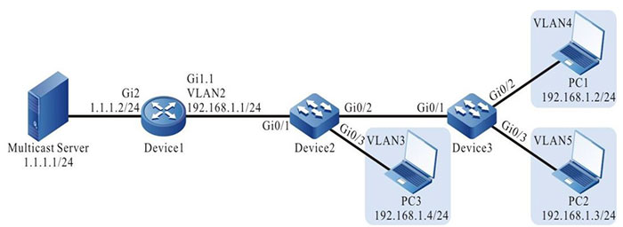
Figure 3-1 MVP typical configuration networking
Configuration Steps
Step 1: Device1 configures the interface IP address and enables the multicast route protocol. (omitted)
Step 2: Configure Device2.
#Create VLAN2-VLAN5 on Device2.
|
Device2#configure terminal
Device2(config)#vlan 2-5
|
#Configure the link type of port gigabitethernet0/1 on Device2 as Trunk, permitting the services of VLAN2 to pass; PVID is configured as 1.
|
Device2(config)#interface gigabitethernet 0/1
Device2(config-if-gigabitethernet0/1)#switchport mode trunk
Device2(config-if-gigabitethernet0/1)#switchport trunk allowed vlan add 2
Device2(config-if-gigabitethernet0/1)# switchport trunk pvid vlan 1
Device2(config-if-gigabitethernet0/1)#exit
|
#Configure the link type of port gigabitethernet0/2 on Device2 as Trunk, permitting the services of VLAN4-VLAN5 to pass; PVID is configured as 1.
|
Device2(config)#interface gigabitethernet 0/2
Device2(config-if-gigabitethernet0/2)#switchport mode trunk
Device2(config-if-gigabitethernet0/2)#switchport trunk allowed vlan add 4-5
Device2(config-if-gigabitethernet0/2)# switchport trunk pvid vlan 1
Device2(config-if-gigabitethernet0/2)#exit
|
#Configure the link type of port gigabitethernet0/3 on Device2 as Access, permitting the services of VLAN3 to pass.
|
Device2(config)#interface gigabitethernet 0/3
Device2(config-if-gigabitethernet0/3)#switchport access vlan 3
Device2(config-if-gigabitethernet0/3)#exit
|
#Configure IGMP snooping.
|
Device2(config)#ip igmp snooping
Device2(config)#ip igmp snooping vlan 2
Device2(config)#ip igmp snooping vlan 3
Device2(config)#ip igmp snooping vlan 4
Device2(config)#ip igmp snooping vlan 5
|
#Configure MVP.
|
Device2(config)#multicast-vlan 2 subvlan 3-5
Device2(config)#vlan 2
Device2(config-vlan2)#multicast-vlan enable
Device2(config-vlan2)#exit
|
Step 3: Configure Device3.
#Create VLAN4-VLAN5 on Device3.
|
Device3#configure terminal
Device3(config)#vlan 4-5
|
#Configure the link type of port gigabitethernet0/1 on Device3 as Trunk, permitting the services of VLAN4-VLAN5 to pass; PVID is configured as 1.
|
Device3(config)#interface gigabitethernet 0/1
Device3(config-if-gigabitethernet0/1)#switchport mode trunk
Device3(config-if-gigabitethernet0/1)#switchport trunk allowed vlan add 4-5
Device3(config-if-gigabitethernet0/1)# switchport trunk pvid vlan 1
Device3(config-if-gigabitethernet0/1)#exit
|
#Configure the link type of port gigabitethernet0/2 on Device3 as Access, permitting the services of VLAN4 to pass.
|
Device3(config)#interface gigabitethernet 0/2
Device3(config-if-gigabitethernet0/2)#switchport access vlan 4
Device3(config-if-gigabitethernet0/2)#exit
|
#Configure the link type of port gigabitethernet0/3 on Device3 as Access, permitting the services of VLAN5 to pass.
|
Device3(config)#interface gigabitethernet 0/3
Device3(config-if-gigabitethernet0/3)#switchport access vlan 5
Device3(config-if-gigabitethernet0/3)#exit
|
Step 4: Check the result.
#View the MVP information.
Device2#show multicast-vlan
Multicast Vlan Table
---------------------------
VLAN ID: 2
status: enable
subvlan count: 3
subvlan: 3-5
#PC1, PC2, and PC3 send the IGMPv2 member relation report to add to multicast group 224.1.1.1.
#View the multicast member table of Device2.
Device2#show ip igmp snooping groups
IGMP Snooping Group Membership
Total 3 groups

VLAN ID Interface Name Group Address Expires   Last Reporter  V1 Expires V2 Expires Uptime
------------------------------------------------------------------------------------------
3       gi0/3          224.1.1.1     00:03:54  192.168.1.4    stopped               00:01:18
4       gi0/2          224.1.1.1     00:04:17  192.168.1.2    stopped               00:00:07
5       gi0/2          224.1.1.1     00:03:54  192.168.1.3    stopped               00:01:21
#View the multicast forwarding table of Device2.
Device2#show ip igmp snooping l3_ip_table
Total 1 entry

Flags: M - L2 multicast, S - short of resources

(*, 224.1.1.1)
  Ingress Vlan: 2
  Flags   : M
  L2 Interface List: gigabitethernet0/1
    Egress Vlan Flags  L3 Interface List
    3           M      gigabitethernet0/3
    4           M      gigabitethernet0/2
    5           M      gigabitethernet0/2
#Multicast Server sends the multicast service packet with destination address 224.1.1.1. PC1, PC2 and PC3 can correctly receive the multicast service packet.
 Switch


