Network Requirements
- The whole network runs the PIM-SM protocol.
- Device2 is C-BSR and C-RP.
- The whole network uses OSPF to interact the unicast route.
- The PIM BFD and OSPF BFD detection functions are enabled for the line between Device1 and Device3. After the line fails, the BFD can quickly detect and notify the PIM and OSPF protocols, so that the RPF neighbor from Device3 to the multicast source can quickly switch to Device2.
Network Topology
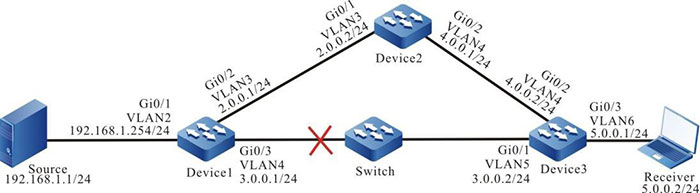
Figure 7-5 Networking of configuring RPF route switching of PIM-SM and BFD linkage
Configuration Steps
Step 1: Configure the IP address of the interface. (omitted)
Step 2: Enable unicast routing protocol, so that all devices in the network can communicate with each other.
#Configure Device1.
|
Device1#configure terminal
Device1(config)#router ospf 100
Device1(config-ospf)#network 2.0.0.0 0.0.0.255 area 0
Device1(config-ospf)#network 3.0.0.0 0.0.0.255 area 0
Device1(config-ospf)#network 192.168.1.0 0.0.0.255 area 0
Device1(config-ospf)#exit
|
#Configure Device2.
|
Device2#configure terminal
Device2(config)#router ospf 100
Device2(config-ospf)#network 2.0.0.0 0.0.0.255 area 0
Device2(config-ospf)#network 4.0.0.0 0.0.0.255 area 0
Device2(config-ospf)#exit
|
#Configure Device3.
|
Device3#configure terminal
Device3(config)#router ospf 100
Device3(config-ospf)#network 3.0.0.0 0.0.0.255 area 0
Device3(config-ospf)#network 4.0.0.0 0.0.0.255 area 0
Device3(config-ospf)#network 5.0.0.0 0.0.0.255 area 0
Device3(config-ospf)#exit
|
#Query the unicast route table of Device3.
Device3#show ip route
Codes: C - connected, S - static, R - RIP, O - OSPF, OE-OSPF External, M - Management
       D - Redirect, E - IRMP, EX - IRMP external, o - SNSP, B - BGP, i-ISIS

Gateway of last resort is not set

C 3.0.0.0/24 is directly connected, 00:01:40, vlan5
C 4.0.0.0/24 is directly connected, 00:00:46, vlan4
C 5.0.0.0/24 is directly connected, 03:45:18, vlan6
C 127.0.0.0/8 is directly connected, 2d:08:42:01, lo0
O 192.168.1.0/24 [110/2] via 3.0.0.1, 00:01:29, vlan5
O 2.0.0.0/24 [110/2] via 4.0.0.1, 00:01:29, vlan4
             [110/2] via 3.0.0.1, 00:01:29, vlan5

-
The viewing methods of Device1 and Device2 are the same as that of Device3, so the viewing process is omitted.
Step 3: Globally enable multicast forwarding, and enable multicast protocol PIM-SM on the interface.
#Configure Device1.
Globally enable multicast forwarding and enable multicast protocol PIM-SM on the related interfaces.
|
Device1(config)#ip multicast-routing
Device1(config)#interface vlan 2
Device1(config-if-vlan2)#ip pim sparse-mode
Device1(config-if-vlan2)#exit
Device1(config)#interface vlan 3
Device1(config-if-vlan3)#ip pim sparse-mode
Device1(config-if-vlan3)#exit
Device1(config)#interface vlan 4
Device1(config-if-vlan4)#ip pim sparse-mode
Device1(config-if-vlan4)#exit
|
#Configure Device2.
Globally enable multicast forwarding and enable multicast protocol PIM-SM on the related interfaces.
|
Device2(config)#ip multicast-routing
Device2(config)#interface vlan 3
Device2(config-if-vlan3)#ip pim sparse-mode
Device2(config-if-vlan3)#exit
Device2(config)#interface vlan 4
Device2(config-if-vlan4)#ip pim sparse-mode
Device2(config-if-vlan4)#exit
|
#Configure Device3.
Globally enable multicast forwarding and enable multicast protocol PIM-SM on the related interfaces.
|
Device3(config)#ip multicast-routing
Device3(config)#interface vlan 4
Device3(config-if-vlan4)#ip pim sparse-mode
Device3(config-if-vlan4)#exit
Device3(config)#interface vlan 6
Device3(config-if-vlan6)#ip pim sparse-mode
Device3(config-if-vlan6)#exit
Device3(config)#interface vlan 5
Device3(config-if-vlan5)#ip pim sparse-mode
Device3(config-if-vlan5)#exit
|
#Query the information of the interface on Device3 enabled with the PIM-SM protocol and the PIM-SM neighbor information.
Device3#show ip pim interface
PIM Interface Table:
PIM VRF Name: Default
Total 3 Interface entries
Total 0 External Interface entry
Total 0 Sparse-Dense Mode Interface entry

Address     Interface            VIF      Ver/      VIF      Nbr       DR       DR
BSR CISCO Neighbor
                                Index    Mode   Flag              CountPri
Border Neighbor Filter
4.0.0.2     vlan4                0    v2/S   UP    1       1
4.0.0.2    FALSE FALSE
5.0.0.1     vlan6                2    v2/S   UP    0       1
5.0.0.1    FALSE FALSE
3.0.0.2     vlan5                3    v2/S   UP    1       1
3.0.0.2    FALSE FALSE

Device3#show ip pim neighbor PIM Neighbor Table:
PIM VRF Name: Default Total 2 Neighbor entries

Neighbor   Interface    Uptime/Expires     Ver DR  Priority/Mode
Address
4.0.0.1    vlan4        00:05:26/00:01:20  v2  1   /
3.0.0.1    vlan5        00:03:51/00:01:24  v2  1   /
Step 4: Configure C-BSR and C-RP.
#Configure Device2.
Configure VLAN3 of Device2 C-BSR and C-RP of the whole network, and the multicast group range of C-RP service is 224.0.0.0/8.
|
Device2(config)#ip pim bsr-candidate vlan 3
Device2(config)#ip pim rp-candidate vlan 3
|
#Query the BSR and RP information of Device3.
Device3#show ip pim bsr-router
PIMv2 Bootstrap information
PIM VRF Name: Default
 BSR address: 2.0.0.2
  BSR Priority: 0
  Hash mask length: 10
  Up time: 00:02:56
  Expiry time: 00:01:14
  Role: Non-candidate BSR
  State: Accept Preferred

Device3#show ip pim rp mapping
PIM Group-to-RP Mappings Table:
PIM VRF Name: Default
Total 1 RP set entry
Total 1 RP entry

  Group(s): 224.0.0.0/4
  RP count: 1
    RP: 2.0.0.2
      Info source: 2.0.0.2, via bootstrap, priority 192
      Up time: 00:02:58
      Expiry time: 00:01:32
Step 5: Configure PIM, OSPF to link with BFD on Device1 and Device3.
#Configure Device1.
|
Device1(config)#interface vlan 4
Device1(config-if-vlan4)#ip pim bfd
Device1(config-if-vlan4)#ip ospf bfd
Device1(config-if-vlan4)#exit
|
#Configure Device3.
|
Device3(config)#interface vlan 5
Device3(config-if-vlan5)#ip pim bfd
Device3(config-if-vlan5)#ip ospf bfd
Device3(config-if-vlan5)#exit
|
#Query the BFD session information of Device3.
Device3#show bfd session detail
Total session number: 1
OurAddr  NeighAddr   LD/RD  State   Holddown Interface
3.0.0.2  3.0.0.1     5/2    UP      5000     vlan5
Type:ipv4 direct

Local State:UP Remote State:UP Up for: 0h:2m:35s Number of times UP:1
Send Interval:1000ms Detection time:5000ms(1000ms*5)
Local Diag:0 Demand mode:0 Poll bit:0
MinTxInt:1000 MinRxInt:1000 Multiplier:5
Remote MinTxInt:1000 Remote MinRxInt:1000 Remote Multiplier:5
Registered protocols:OSPF PIM
Agent session info:
Sender:slot 1 Recver:slot 1
#You can see that the BFD session between Device1 and Device3 is established normally, and OSPF and PIM protocols are successfully associated.
-
The viewing methods of Device1 are the same as that of Device3, so the viewing process is omitted.
Step 6: Check the result.
#Receiver sends the IGMPv2 membership report to join the multicast group 225.1.1.1, and Source sends the multicast service packet with the multicast group 225.1.1.1.
#View the multicast member table of Device3.
Device3#show ip igmp groups
IGMP Connected Group Membership Total 1 groups
Group Address   Interface   Uptime     Expires   Last Reporter V1 Expires V2 Expires
225.1.1.1       vlan6       02:55:24   00:04:18  5.0.0.3       stopped
#Query the PIM-SM multicast route table of Device3.
Device3#show ip pim mroute
IP Multicast Routing Table:
PIM VRF Name: Default
Total 0 (*,*,RP) entry
Total 1 (*,G) entry
Total 1 (S,G) entry
Total 1 (S,G,rpt) entry
Total 0 FCR entry
Up timer/Expiry timer


(*, 225.1.1.1)
Up time: 02:57:30
RP: 2.0.0.2
RPF nbr: 4.0.0.1
RPF idx: vlan4
Flags:
  JOIN DESIRED
Upstream State: JOINED
  Local interface list:
     vlan6
  Joined interface list:
  Asserted interface list:


(192.168.1.1, 225.1.1.1)
Up time: 00:12:58
KAT time: 00:03:03
RPF nbr: 3.0.0.1
RPF idx: vlan5
SPT bit: TRUE
Flags:
  JOIN DESIRED
Upstream State: JOINED
  Local interface list:
  Joined interface list:
  Asserted interface list:
  Outgoing interface list:
     vlan6
  Packet count 620657

(192.168.1.1, 225.1.1.1, rpt)
Up time: 00:12:58
RP: 2.0.0.2
Flags:
  RPT JOIN DESIRED
  RPF SGRPT XG EQUAL
Upstream State: NOT PRUNED
  Local interface list:
  Pruned interface list:
  Outgoing interface list:
##You can see that the RPF neighbor from Device3 to multicast source is Device1, and the ingress interface of multicast service packet is vlan5.
#When the line between Device1 and Device3 fails, BFD will quickly detect and notify OSPF and PIM protocol, OSPF will switch the route to Device2 for communication, and notify PIM protocol of unicast route change, PIM protocol will quickly switch to the RPF neighbor of multicast source.
#View the PIM-SM neighbor and multicast roue table of device3.
Apr 27 2016 06:59:26: %BFD-SESSION_DOWN-4: Session [destination address:3.0.0.1,source address:3.0.0.2,interface:vlan5,local-discriminator:4] DOWN
Device3#show ip pim neighbor
PIM Neighbor Table:
PIM VRF Name: Default
Total 1 Neighbor entry

Neighbor    Interface   Uptime/Expires     Ver DR  Priority/Mode
Address
4.0.0.1     vlan4       00:34:40/00:01:37  v2  1   /

Device3#show ip pim mroute
IP Multicast Routing Table:
PIM VRF Name: Default
Total 0 (*,*,RP) entry
Total 1 (*,G) entry
Total 1 (S,G) entry
Total 1 (S,G,rpt) entry
Total 0 FCR entry
Up timer/Expiry timer

(*, 225.1.1.1)
Up time: 03:07:04 RP: 2.0.0.2
RPF nbr: 4.0.0.1
RPF idx: vlan4
Flags:
  JOIN DESIRED
Upstream State: JOINED
  Local interface list:
    vlan6
  Joined interface list:
  Asserted interface list:


(192.168.1.1, 225.1.1.1)
Up time: 00:22:32
KAT time: 00:03:29
RPF nbr: 4.0.0.1
RPF idx: vlan4
SPT bit: TRUE
Flags:
  JOIN DESIRED
Upstream State: JOINED
  Local interface list:
  Joined interface list:
  Asserted interface list:
  Outgoing interface list:
     vlan6
  Packet count 1127697

(192.168.1.1, 225.1.1.1, rpt)
Up time: 00:22:32
RP:2.0.0.2
Flags:
  RPT JOIN DESIRED
  RPF SGRPT XG EQUAL
Upstream State: NOT PRUNED
  Local interface list:
  Pruned interface list:
  Outgoing interface list:
vlan6
#You can see that the RPF neighbor from Device3 to multicast source is switched to Device2, and the ingress interface of multicast service packet is vlan4.
-
Because the RPF route convergence of PIM and BFD linkage depends on the convergence speed of unicast routing, BFD also needs to link with the related unicast routing protocol OSPF.
 Switch


