Configure ULFD Basic Function
Network Requirements
- Device1 and Device2 are connected via the fiber.
- Configure the ULFD aggressive mode to disable the port when detecting the uni-directional link.
Network Topology
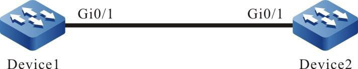
Figure 2-3 Networking of configuring the ULFD basic function
Configuration Steps
Step 1: Configure the ULFD function
#Enable the ULFD function on Device1 and configure the ULFD work mode as the aggressive mode on port gigabitethernet0/1.
|
Device1#configure terminal
Device1(config)#ulfd aggressive
Device1(config)#interface gigabitethernet 0/1
Device1(config-if-gigabitethernet0/1)#ulfd port aggressive
Device1(config-if-gigabitethernet0/1)#exit
|
#Enable the ULFD function on Device2 and configure the ULFD work mode on port gigabitethernet0/1 as the aggressive mode.
|
Device2#configure terminal
Device2(config)#ulfd aggressive
Device2(config)#interface gigabitethernet 0/1
Device2(config-if-gigabitethernet0/1)#ulfd port aggressive
Device2(config-if-gigabitethernet0/1)#exit
|
#View the ULFD information of port gigabitethernet0/1 on Device1.
Device1#show ulfd interface gigabitethernet 0/1
Interface name     : gigabitethernet0/1
ULFD config mode   : Aggressive
ULFD running mode  : Aggressive
Link status        : Link Up
Link direction     : Bidirectional
ULFD fsm status    : Advertisement

Neighbors number : 1
---------------------
   Device ID          : 00017a787878
   Interface name     : gigabitethernet0/1
   Device Name        : Device2
   Message Interval   : 15
   Timeout Interval   : 5
   Link Direction     : Bidirectional
   Aging Time         : 40
   Time to Die        : 36
 -------------------------------------

-
The method of viewing the port ULFD information on Device2 is the same as that of Device1. (Omitted)
Step 2: Check the result.
#In the actual networking environment (refer to Figure 2-1 and Figure 2-2), when the fibers are cross-connected or one fiber is not connected, disconnected, it results in the uni-directional communication. After configuring the ULFD function, port gigabitethernet0/1 is disabled when detecting the uni-directional connection on Device1 and the following log information is output:
|
%ULFD_LOG_WARN: gigabitethernet0/1: detected Unidirectional neighbor: device ID[00017a787878], device name[Device2], interface name[gigabitethernet0/1]!
%LINK-INTERFACE_DOWN-3: interface gigabitethernet0/1, changed state to down
%ULFD-UNDIR_LINK_ERR_V3-4: ULFD shutdown interface gigabitethernet0/1 successful
|
#View the status of the port gigabitethernet0/1 and we can see that the port is disabled.
Device1#show interface gigabitethernet 0/1
gigabitethernet0/1 configuration information
        Description      :
        Status           : Enabled
        Link             : Down (Err-disabled)
        Set Speed        : Auto
        Act Speed        : Unknown
        Set Duplex       : Auto
        Act Duplex       : Unknown
        Set Flow Control : Off
        Act Flow Control : Off
        Mdix             : Normal
        Mtu              : 1824
        Port mode        : LAN
        Port ability     : 100M FD,1000M FD
        Link Delay       : No Delay
        Storm Control    : Unicast Disabled
        Storm Control    : Broadcast Disabled
        Storm Control    : Multicast Disabled
        Storm Action     : None
        Port Type        : Nni
        Pvid             : 1
        Set Medium       : Fiber
        Act Medium       : Fiber
        Mac Address      : 0000.1111.2224
-
When configuring the ULFD function, ensure that ULFD configured at the two sides of the link work in the same detection mode.
- When ULFD common work mode is normal mode, refer to the configuration method. The normal mode only supports detecting the single-pass caused by the cross-connection of the fiber.
 Switch


