Network Requirements
- The OSPF neighbor is established between Device3 and Device2 and the interface directly connected routing 200.0.0.0/24 and 210.0.0.0/24 are advertised to Device2.
- The IRMP neighbor is established between Device1 and Device2. When Device2 redistributing the OSPF routing to the IRMP, only the routing 200.0.0.0/24 instead of the routing 210.0.0.0/24 is advertised to Device1 through the routing policy control.
Network Topology
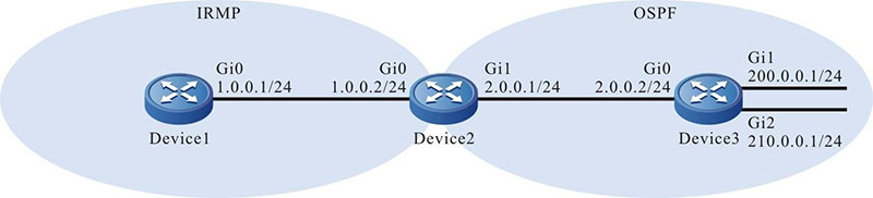
Figure 11–2 Networking of the IRMP route redistribution
Configuration Steps
Step 1: Configure the IP address of the interfaces. (Omitted)
Step 2: Configure the OSPF.
#Configure Device2.
|
Device2#configure terminal
Device2(config)#router ospf 100
Device2(config-ospf)#network 2.0.0.0 0.0.0.255 area 0
Device2(config-ospf)#exit
|
#Configure Device3.
|
Device3#configure terminal
Device3(config)#router ospf 100
Device3(config-ospf)#network 2.0.0.0 0.0.0.255 area 0
Device3(config-ospf)#network 200.0.0.0 0.0.0.255 area 0
Device3(config-ospf)#network 210.0.0.0 0.0.0.255 area 0
Device3(config-ospf)#exit
|
#View the routing table of Device2.
Device2#show ip route
Codes: C - connected, S - static, R - RIP, O - OSPF, OE-OSPF External, M - Management
       D - Redirect, E - IRMP, EX - IRMP external, o - SNSP, B - BGP, i-ISIS

Gateway of last resort is not set

C 1.0.0.0/24 is directly connected, 07:39:21, gigabitethernet0
C 2.0.0.0/24 is directly connected, 00:03:36, gigabitethernet1
C 127.0.0.0/8 is directly connected, 57:04:58, lo0
O 200.0.0.0/24 [110/2] via 2.0.0.2, 00:01:10, gigabitethernet1
O 210.0.0.0/24 [110/2] via 2.0.0.2, 00:01:10, gigabitethernet1
In the routing table, it can be viewed that Device2 learns the OSPF routing 200.0.0.0/24 and 210.0.0.0/24 advertised by Device3.
Step 3: Configure the IRMP.
#Configure Device1.
|
Device1#configure terminal
Device1(config)#router irmp 100
Device1(config-irmp)#network 1.0.0.0 0.0.0.255
Device1(config-irmp)#exit
|
#Configure Device2.
|
Device2(config)#router irmp 100
Device2(config-irmp)#network 1.0.0.0 0.0.0.255
Device2(config-irmp)#exit
|
#View the IRMP neighbor informatione of Device1.
Device1#show ip irmp neighbor
IP-IRMP neighbors for process 100 Total neighbor 1
Address   Interface         Hold(s) Uptime     SeqNum   Srtt(ms) Rto(s)
1.0.0.2   gigabitethernet0  12      00:01:03   1        0        2
The IRMP neighbor is successfully established between Device1 and Device2.
Step 4: Configure the IRMP to redistribute the OSPF routing and to coordinate with the routing policy.
#Configure the routing policy to match the ACL only permitting the routing 200.0.0.0/24 on Device2 and to coordinate with the routing policy when the IRMP redistributing the OSPF routing.
|
Device2(config)#ip access-list standard 1
Device2(config-std-nacl)#permit 200.0.0.0 0.0.0.255
Device2(config-std-nacl)#exit
Device2(config)#route-map ospf_to_irmp
Device2(config-route-map)#match ip address 1
Device2(config-route-map)#exit
Device2(config)#router irmp 100
Device2(config-irmp)#redistribute ospf 100 route-map ospf_to_irmp
Device2(config-irmp)#exit
|

-
When configuring the routing policy, both the prefix list and ACL can establish the matching rule. The difference lies in that the prefix list can accurately match the route mask, but the ACL cannot match the route mask.
Step 5: Check the result.
#View the IRMP topology table of Device2.
Device2#show ip irmp topology
IP-IRMP Topology Table for process 100
Codes: P - Passive, A - Active, H - Holddown, D - Hidden
        > - FIB route, * - FIB successor

P >1.0.0.0/24, 1 successors, FD is 2816
        *via Connected (2816/0), gigabitethernet0
P 200.0.0.0/24, 1 successors, FD is 2816
         via RedisOSPF 100 (2816/0)
It can be viewed that Device2 successfully distributes the OSPF routing to the IRMP.
#View the topology table and routing table of Device1.
Device1#show ip irmp topology
IP-IRMP Topology Table for process 100
Codes: P - Passive, A - Active, H - Holddown, D - Hidden
        > - FIB route, * - FIB successor

P >1.0.0.0/24, 1 successors, FD is 2816
        *via Connected (2816/0), gigabitethernet0
P >200.0.0.0/24, 1 successors, FD is 3072
        *via 1.0.0.2 (3072/2816), gigabitethernet0

Device1#show ip route
Codes: C - connected, S - static, R - RIP, O - OSPF, OE-OSPF External, M - Management
       D - Redirect, E - IRMP, EX - IRMP external, o - SNSP, B - BGP, i-ISIS

Gateway of last resort is not set

C 1.0.0.0/24 is directly connected, 07:47:01, gigabitethernet0
C 127.0.0.0/8 is directly connected, 07:55:23, lo0
Ex 200.0.0.0/24 [170/3072] via 1.0.0.2, 00:00:06, gigabitethernet0
It can be viewed that Device1 learns the routing 200.0.0.0/24.

-
In the actual application, if there are two or more edge routers in the autonomous system, you are advised to not redistribute routes between different routing protocols. If necessary, configure the routing control policies such as filtering and summary on the edge router in the autonomous system to prevent generating routing loop.
 Switch


