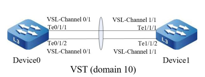
Network Requirement
- Device0, and Device1 form the link stacking system; Device0 becomes the control device.
Network Topology

Figure 1-2 Configure devices to form the link stacking system
Configuration Steps
Step 1: Configure Device0.
#On Device0, configure the virtual switching member device number as 0, configure the domain number as 10, and the priority is 255.
|
Device0#configure terminal
Device0(config)#switch virtual member 0
Do you want to modify member id(Yes|No)?y
% Member ID 0 config will take effect only after the exec command 'switch mode virtual' is issued
Device0(config-vst-member-0)#domain 10
% Domain ID 10 config will take effect only after the exec command 'switch mode virtual' is issued
Device0(config-vst-member-0)#priority 255
Device0(config-vst-member-0)#exit
|
#On Device0, create virtual switch link interface 1 and add port tengigabitethernet1/1 and tengigabitethernet1/2 to the virtual switch link interface 1.
|
Device0(config)#vsl-channel 1
Device0(config-vsl-channel-1)#exit
Device0(config)#interface tengigabitethernet 1/1-1/2
Device0(config-if-range)#vsl-channel 1 mode on
Device0(config-if-range)#exit
|
#Save the configuration on Device0.
|
Device0#write
Are you sure to overwrite /flash/startup (Yes|No)?y
Building Configuration...done
Write to startup file OK
Write to mode file OK
|
Step 2: Configure Device1.
#On Device1, configure the virtual switching member device number as 1, configure the domain number as 10, and the priority is 200.
|
Device1#configure terminal
Device1(config)#switch virtual member 1
Do you want to modify member id(Yes|No)?y
% Member ID 1 config will take effect only after the exec command 'switch mode virtual' is issued
Device1(config-vst-member-1)#domain 10
% Domain ID 10 config will take effect only after the exec command 'switch mode virtual' is issued
Device1(config-vst-member-1)#priority 200
Device1(config-vst-member-1)#exit
|
#On Device1, create virtual switch link interface 1 and add port tengigabitethernet0/1 and tengigabitethernet0/2 to the virtual switch link interface 1.
|
Device1(config)#vsl-channel 1
Device1(config-vsl-channel-1)#exit
Device1(config)#interface tengigabitethernet 0/1-0/2
Device1(config-if-range)#vsl-channel 1 mode on
Device1(config-if-range)#exit
|
#On Device1, save the configuration.
|
Device1#write
Are you sure to overwrite /flash/startup (Yes|No)?y
Building Configuration...done
Write to startup file... OK
Write to mode file... OK
|
Step 3: Configure the running mode of Device0 and Device1 as the VST mode.
#Configure the running mode of Device0 as the VST mode.
Device0#switch mode virtual
This command will convert all interface names to naming convention "interface-type member-number/slot/interface" ,
Please make sure to save current configuration.Do you want to proceed? (yes|no)?y
Converting interface names Building configuration
Copying the startup configuration to backup file named "startup-backupalone"
Please wait	system reloading is in progress!
 ok
Reset system!
Jul 30 2014 17:36:14: %SYS-5-RELOAD: Reload requested
#Configure the running mode of Device1 as the VST mode.
Device1#switch mode virtual
This command will convert all interface names to naming convention "interface-type member-number/slot/interface" ,
Please make sure to save current configuration.Do you want to proceed? (yes|no)?y
Converting interface names Building configuration
Copying the startup configuration to backup file named "startup-backupalone"
Please wait	system reloading is in progress!
 ok
Reset system!
Jul 30 2014 17:36:20: %SYS-5-RELOAD: Reload requested
Step 4: Check the result.
#On Device0, the VST system is formed and Device0 is the master device.
Device0#show switch virtual
Codes: L - local-device,I isolate-device

Virtual Switch Mode          : VIRTUAL
Virtual Switch DomainId      : 10
Virtual Switch mac-address.. 0001.7a6a.001b

---------------VST MEMBER INFORMATION--------------------
CODE  MemberID  Role    Pri  LocalVsl         RemoteVsl
L     0         Master  255  vsl-channel 0/1  vsl-channel 1/1
      1         Member  200  vsl-channel 1/1  vsl-channel 0/1
 Switch
 Wifi - Access Point
 Firewall
 Router
 Module Quang
![Module Quang Cisco]() Module Quang Cisco
Module Quang Cisco![Module quang HPE]() Module quang HPE
Module quang HPE![Module quang Maipu]() Module quang Maipu
Module quang Maipu![Module quang Brocade]() Module quang Brocade
Module quang Brocade![Module quang Fortinet]() Module quang Fortinet
Module quang Fortinet![Module quang Aruba]() Module quang Aruba
Module quang Aruba![Module quang OEM]() Module quang OEM
Module quang OEM![Module quang Juniper]() Module quang Juniper
Module quang Juniper![Module quang Dell]() Module quang Dell
Module quang Dell![Module quang Palo Alto]() Module quang Palo Alto
Module quang Palo Alto![Module quang Huawei]() Module quang Huawei
Module quang Huawei![Module quang Arista]() Module quang Arista
Module quang Arista![Module quang F5]() Module quang F5
Module quang F5![Module quang H3C]() Module quang H3C
Module quang H3C![Module Quang Allied Telesis]() Module Quang Allied Telesis
Module Quang Allied Telesis![Module quang SonicWall]() Module quang SonicWall
Module quang SonicWall![Module quang Mikrotik]() Module quang Mikrotik
Module quang Mikrotik![Module quang Handar]() Module quang Handar
Module quang Handar Máy chủ (Server)
 Thiết bị lưu trữ (SAN, NAS)
 Load Balancing
 Video Conferencing
 Phụ kiện máy chủ
 Thiết Bị IoT
 Phụ Kiện Mạng


.png)


