Network Requirements
- On Device1, configure two static routes to reach network segment 192.168.1.1/32. One route passes Device2, and the other passes Device3. Device1 first uses the route that passes Device3 to forward packets.
- On Device1, configure a static recursive route to reach network segment 200.0.0.0/24, with the gateway address being the loopback interface address 192.168.1.1 of Device3. After the route between Device1 and Device3 is faulty, Device1 switches to the route that passes Device2 for communication.
Network Topology
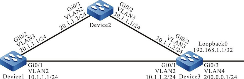
Figure 3-4 Networking for Configure a Static Recursive Static Route
Configuration Steps
Step 1: Create VLANs, and add ports to the required VLANs. (Omitted)
Step 2: Configure IP addresses for the ports. (Omitted)
Step 3: Configure static routes.
#Configure Device1.
|
Device1#configure terminal
Device1(config)#ip route 192.168.1.1 255.255.255.255 10.1.1.2
Device1(config)#ip route 192.168.1.1 255.255.255.255 20.1.1.2 10
|
#Configure Device2.
|
Device2#configure terminal
Device2(config)#ip route 192.168.1.1 255.255.255.255 30.1.1.2
|
Step 4: Configure a static recursive route.
#Configure Device1.
|
Device1(config)#ip route 200.0.0.0 255.255.255.0 192.168.1.1
|
#Query the routing table of Device1.
Device1#show ip route
Codes: C - connected, S - static, R - RIP, O - OSPF, OE-OSPF External, M - Management
       D - Redirect, E - IRMP, EX - IRMP external, o - SNSP, B - BGP, i-ISIS

Gateway of last resort is not set

C 10.1.1.0/24 is directly connected, 00:04:07, vlan2
C 20.1.1.0/24 is directly connected, 00:03:58, vlan3
C 127.0.0.0/8 is directly connected, 73:10:12, lo0
S 200.0.0.0/24 [1/100] via 192.168.1.1, 00:00:08, vlan2
S 192.168.1.1/32 [1/100] via 10.1.1.2, 00:01:46, vlan2
According to the routing table, the gateway address of the route to 200.0.0.0/24 is 192.168.1.1, the output interface is VLAN2, and the route relies on the route to 192.168.1.1/32.
Step 5: Check the result.
#After the route between Device1 and Device3 becomes faulty, query the routing table of Device1.
Device1#show ip route
Codes: C - connected, S - static, R - RIP, O - OSPF, OE-OSPF External, M Management
       D - Redirect, E - IRMP, EX - IRMP external, o - SNSP, B BGP, i-ISIS

Gateway of last resort is not set

C 20.1.1.0/24 is directly connected, 00:09:04, vlan3
C 127.0.0.0/8 is directly connected, 73:15:18, lo0
S 200.0.0.0/24 [1/100] via 192.168.1.1, 00:00:02, vlan3
S 192.168.1.1/32 [10/100] via 20.1.1.2, 00:00:02, vlan3
Comparing the routing table information with the routing table information in Step 3, the output interface has changed to VLAN3, indicating that the route has been switched to the route to Device2.
 Switch


