Network Requirements
- On Device1 and Device2, create one VRRP load-balance backup group, making Device1 and Device2 share one virtual IP address and realizing the backup for the default gateway of the user host, so as to reduce the interruption time of the network.
- The VRRP load-balance protocol realizes the load function by distributing the traffic from different user hosts to different VRRP devices in a group. The significant difference from the common VRRP is that backup devices in the VRRP load-balance protocol can also forward the traffic, which enables users to configure the same gateway address for all hosts in the network to achieve load balancing.
Network Topology
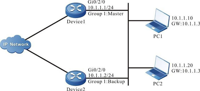
Figure 8-1 Networking of configuring the basic functions of the VRRP load-balance protocol
Configuration Steps
Step 1: Configure the IPv4 address of the interface (omitted).
Step 2: Configure the device as the VRRP load-balance protocol mode.
#Configure Device1.
|
Device1#configure terminal
Device1(config)#vrrp mode load-balance
|
#Configure Device2.
|
Device2#configure terminal
Device2(config)#vrrp mode load-balance
|
#Query the VRRP protocol mode of Device1.
Device1#show vrrp-pub mode

Current mode:load_balance
Current switch:0
#Query the VRRP protocol mode of Device2.
Device2#show vrrp-pub mode

Current mode:load_balance
Current switch:0
You can see that both Device1 and Device2 run in the VRRP load-balance protocol mode.
Step 3: Create one VRRP load-balance protocol backup group.
#On Device1, create backup group 1. The virtual IP address is 10.1.1.3, and configure the priority as 110.
|
Device1(config)#interface gigabitethernet 0/2/0
Device1(config-if-gigabitethernet0/2/0)#vrrp 1 ip 10.1.1.3
Device1(config-if-gigabitethernet0/2/0)#vrrp 1 priority 110
Device1(config-if-gigabitethernet0/2/0)#exit
|
#On Device2, create backup group 1, and the virtual IP address is 10.1.1.3
|
Device2(config)#interface gigabitethernet 0/2/0
Device2(config-if-gigabitethernet0/2/0)#vrrp 1 ip 10.1.1.3
Device2(config-if-gigabitethernet0/2/0)#exit
|
Step 4: Query the status of the VRRP load-balance protocol.
#Query the VRRP load-balance protocol neighbor table of Device1.
Device1#show vrrp neighbor

 Gid Neighbor  Priority Uid     Virtual-ip  Master    Hold-time  Interface
 1   10.1.1.2  100      412780  10.1.1.3....10.1.1.1  36         gigabitethernet0/2/0
From the Neighbor field, you can see that Device1 successfully sets up the neighbor with Device2.
#Query the VRRP load-balance protocol neighbor table of Device2.
Device2#show vrrp neighbor

 Gid Neighbor  Priority Uid     Virtual-ip  Master    Hold-time  Interface
 1   10.1.1.1  110      348619  10.1.1.3....10.1.1.1  33         gigabitethernet0/2/0
From the Neighbor field, you can see that Device2 also sets up the neighbor with Device1 successfully.
#Query the VRRP load-balance protocol status of Device1.
Device1#show vrrp
Interface gigabitethernet0/2/0
    Vrf:0
    Virtual router : 1
        Mac mode: real mac mode
        Forwording mac :
            00.01.7a.7c.72.26
        Virtual IP address : 10.1.1.3
        Match address : 10.1.1.1
        State : Master
        Priority : 110
        Hello interval(sec) : 10
            next hello in 3 secs
        Hold time(sec) :      40
        Delay vote time(sec) : 40
        Delay delete time(sec) : 20
        Preserve time(sec) : 40
        Keep(min) : 15
        Zombie(min) : 10
        Uid : 348619
        Terminal number : 0/1000
From the State field, you can see that Device1 is elected as Master.
#Query the VRRP load-balance protocol status of Device2.
Device2#show vrrp
Interface gigabitethernet0/2/0
    Vrf:0
    Virtual router : 1
        Mac mode: real mac mode
        Forwording mac :
            00.01.7a.ff.ff.00
        Virtual IP address : 10.1.1.3
        Match address : 10.1.1.2
        State : Backup
        master:10.1.1.1
        Priority : 100
        Hello interval(sec) : 10
            next hello in 6 secs
        Hold time(sec) :      40
        Delay vote time(sec) : 40
        Delay delete time(sec) : 20
        Preserve time(sec) : 40
        Keep(min) : 15
        Zombie(min) : 10
        Uid : 412780
        Terminal number : 0
From the State field, you can see that Device2 becomes Backup.
#On Device1, query the VRRP load-balance protocol forwarding the MAC address distributing table.
Device1# show vrrp fmac

 Gid Virtual-ip Forwarding-mac   Owner     Backup Owner-state Timeout Interface

 1   10.1.1.3   0001.7a7c.7226   10.1.1.1  -      Active---------------gigabitethernet0/2/0

 1   10.1.1.3   0001.7aff.ff00   10.1.1.2  -      Active---------------gigabitethernet0/2/0
Only Master has the function of distributing the forwarding MAC address. From the corresponding relationship between Owner and Forwarding-mac, it can be seen that the forwarding MAC address allocated for 10.1.1.1 is 0001.7a7c.7226, and the forwarding MAC address allocated for 10.1.1.2 is 0001.7aff.ff00.

-
VRRP load balancing protocol can only work in non-preempt mode.
- VRRP load balancing protocol starts the delay election timer in the init state, and by default, it is four times of the Hello interval. Elect after timeout.
- VRRP load balancing protocol elects according to the priority. The one with the highest priority is elected as Master If the priorities are the same, compare the IP addresses of the interfaces. The one with largest IP address is elected as Master, and the others are Backup.
Step 5: Check the result.
#On PC1 and PC2, ping the gateway to test the connectivity. On Device1, query the gateway forwarding MAC address distributed by Master for the host.
Device1#show vrrp terminal

  Gid  Virtual-ip    Terminal       Forwarding-mac  Interface
  1    10.1.1.3      10.1.1.10	    0001.7a7c.7226  gigabitethernet0/2/0
  1    10.1.1.3      10.1.1.20      0001.7aff.ff00  gigabitethernet0/2/0
As shown in the table above, the host terminals PC1 and PC2 are assigned with different gateway forwarding MAC addresses. Combined with the forwarding MAC addresses allocated by Master for Device 1 and Device 2 in Step 4, it can be seen that the traffic of PC1 and PC2 is forwarded by Device 1 and Device 2 respectively to achieve load balancing.
#On Device2, query the forwarding MAC address distributing table of the Backup terminal gateway.
Device2#show vrrp terminal

  Gid  Virtual-ip    Terminal       Forwarding-mac  Interface
  1    10.1.1.3      10.1.1.10      0001.7a7c.7226  gigabitethernet0/2/0
  1    10.1.1.3      10.1.1.20      0001.7aff.ff00  gigabitethernet0/2/0
Master synchronizes the forwarding MAC address distributing table of the terminal gateway to all VRRP devices.
 Switch


