Network Requirements
- The whole network includes two AS: AS100 and AS200. Run the BGP protocol between Ass and use MBGP to interact the multicast route; in AS, run the OSPF protocol to interact the route.
- Multicast domain PIM-SM1 is located in AS100; multicast domain PIM-SM2 is located in AS200. Source is one multicast source of PIM-SM1. Receiver is one receiver of PIM-SM2.
- Loopback1 of Device2 is C-BSR of PIM-SM1 and Loopback0 of Device2 is C-RP of PIM-SM1. Loopback1 of Device3 is C-BSR of PIM-SM2 and Loopback0 of Device3 is C-RP of PIM-SM2.
- Between Device2 and Device3, set up the MSDP peer connection, so as to realize the cross-domain forwarding of the multicast service packet, so that Receiver can receive the multicast service packet sent by Source.
Network Topology
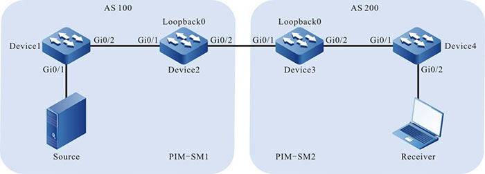
Figure 8-1 Networking of configuring the inter-PIM-SM domain multicast
|
Device
|
Interface
|
VLAN
|
IP Address
|
|
Device1
|
Gi0/1
|
2
|
10.1.1.1/24
|
|
|
Gi0/2
|
3
|
10.1.2.1/24
|
|
Device2
|
Gi0/1
|
3
|
10.1.2.2/24
|
|
Device2
|
Gi0/2
|
4
|
10.1.3.1/24
|
|
|
Loopback0
|
|
11.11.11.11/32
|
|
|
Loopback1
|
|
12.12.12.12/32
|
|
Device3
|
Gi0/1
|
4
|
10.1.3.2/24
|
|
|
Gi0/2
|
5
|
10.1.4.1/24
|
|
|
Loopback0
|
|
22.22.22.22/32
|
|
|
Loopback1
|
|
12.12.12.12/32
|
|
Device4
|
Gi0/1
|
5
|
10.1.4.2/24
|
|
|
Gi0/2
|
6
|
10.1.5.1/24
|
|
Source
|
|
|
10.1.1.2/24
|
Configuration Steps
Step 1: Configure VLAN and add the port to the corresponding VLAN. (omitted)
Step 2: Configure the IP address of the interface. (omitted)
Step 3: Configure OSPF so that all devices in the AS domain can communicate with each other.
#Configure Device1.
|
Device1#configure terminal
Device1(config)#router ospf 100
Device1(config-ospf)#network 10.1.1.0 0.0.0.255 area 0
Device1(config-ospf)#network 10.1.2.0 0.0.0.255 area 0
Device1(config-ospf)#exit
|
#Configure Device2.
|
Device2#configure terminal
Device2(config)#router ospf 100
Device2(config-ospf)#network 10.1.2.0 0.0.0.255 area 0
Device2(config-ospf)#network 11.11.11.11 0.0.0.0 area 0
Device2(config-ospf)#network 12.12.12.12 0.0.0.0 area 0
Device2(config-ospf)#exit
|
#Configure Device3.
|
Device3#configure terminal
Device3(config)#router ospf 100
Device3(config-ospf)#network 10.1.4.0 0.0.0.255 area 0
Device3(config-ospf)#network 22.22.22.22 0.0.0.0 area 0
Device3(config-ospf)#network 23.23.23.23 0.0.0.0 area 0
Device3(config-ospf)#exit
|
#Configure Device4.
|
Device4#configure terminal
Device4(config)#router ospf 100
Device4(config-ospf)#network 10.1.4.0 0.0.0.255 area 0
Device4(config-ospf)#network 10.1.5.0 0.0.0.255 area 0
Device4(config-ospf)#exit
|
#View the route table of Device1.
Device1#show ip route
Codes: C - connected, S - static, R - RIP, O - OSPF, OE-OSPF External, M - Management
       D - Redirect, E - IRMP, EX - IRMP external, o - SNSP, B - BGP, i-ISIS

Gateway of last resort is not set

C 10.1.1.0/24 is directly connected, 00:05:44, vlan2
C 10.1.2.0/24 is directly connected, 22:24:35, vlan3
O 11.11.11.11/32 [110/2] via 10.1.2.2, 01:21:25, vlan3
O 12.12.12.12/32 [110/2] via 10.1.2.2, 01:19:25, vlan3
#View the route table of Device4.
Device4#show ip route
Codes: C - connected, S - static, R - RIP, O - OSPF, OE-OSPF External, M Management
       D - Redirect, E - IRMP, EX - IRMP external, o - SNSP, B BGP, i-ISIS

Gateway of last resort is not set

C 10.1.4.0/24 is directly connected, 22:41:14, vlan5
C 10.1.5.0/24 is directly connected, 00:08:11, vlan6
O 22.22.22.22/32 [110/2] via 10.1.4.1, 01:23:33, vlan5
O 23.23.23.23/32 [110/2] via 10.1.4.1, 01:19:33, vlan5
You can see that Device1 and Device4 only learn the routes of the belonging AS domain.

-
The viewing method of Device2 and Device3 is the same as that of Device1, Device4, so the viewing process is omitted.
Step 4: Globally enable the multicast forwarding, enable the multicast protocol PIM-SM on the interface, and configure C-BSR and C-RP.
#Configure Device1.
Globally enable the multicast forwarding, and enable the multicast protocol PIM-SM on the interfaces.
|
Device1(config)#ip multicast-routing
Device1(config)#interface vlan 2
Device1(config-if-vlan2)#ip pim sparse-mode
Device1(config-if-vlan2)#exit
Device1(config)#interface vlan 3
Device1(config-if-vlan3)#ip pim sparse-mode
Device1(config-if-vlan3)#exit
|
#Configure Device2.
Globally enable the multicast forwarding, enable the multicast protocol PIM-SM on the interface, and configure Loopback1 as C-BSR and Loopback0 as C-RP; the multicast group range of the C-RP service is 224.0.0.0/4.
|
Device2(config)#ip multicast-routing
Device2(config)#interface loopback 0
Device2(config-if-loopback0)#ip pim sparse-mode
Device2(config-if-loopback0)#exit
Device2(config)#interface loopback 1
Device2(config-if-loopback1)#ip pim sparse-mode
Device2(config-if-loopback1)#exit
Device2(config)#interface vlan 3
Device2(config-if-vlan3)#ip pim sparse-mode
Device2(config-if-vlan3)#exit
Device2(config)#interface vlan 4
Device2(config-if-vlan4)#ip pim sparse-mode
Device2(config-if-vlan4)#exit
Device2(config)#ip pim bsr-candidate loopback1
Device2(config)#ip pim rp-candidate loopback0
|
#Configure Device3.
Globally enable the multicast forwarding, enable the multicast protocol PIM-SM on the interface, and configure Loopback1 as C-BSR and Loopback 0 as C-RP; the multicast group range of the C-RP service is 224.0.0.0/4.
|
Device3(config)#ip multicast-routing
Device3(config)#interface loopback 0
Device3(config-if-loopback0)#ip pim sparse-mode
Device3(config-if-loopback0)#exit
Device3(config)#interface loopback 1
Device3(config-if-loopback1)#ip pim sparse-mode
Device3(config-if-loopback1)#exit
Device3(config)#interface vlan 4
Device3(config-if-vlan4)#ip pim sparse-mode
Device3(config-if-vlan4)#exit
Device3(config)#interface vlan 5
Device3(config-if-vlan5)#ip pim sparse-mode
Device3(config-if-vlan5)#exit
Device3(config)#ip pim bsr-candidate loopback 1
Device3(config)#ip pim rp-candidate loopback0
|
#Configure Device4.
Globally enable the multicast forwarding, and enable the multicast protocol PIM-SM on the interfaces.
|
Device4(config)#ip multicast-routing
Device4(config)#interface vlan 5
Device4(config-if-vlan5)#ip pim sparse-mode
Device4(config-if-vlan5)#exit
Device4(config)#interface vlan 6
Device4(config-if-vlan6)#ip pim sparse-mode
Device4(config-if-vlan6)#exit
|
#View the information of the interface enabled with the PIM-SM protocol on Device4 and the PIM-SM neighbor information.
Device4#show ip pim interface
PIM Interface Table:
PIM VRF Name: Default
Total 3 Interface entries
Total 0 External Interface entry
Total 0 Sparse-Dense Mode Interface entry

Address     Interface            VIF      Ver/      VIF      Nbr       DR       DR
BSR CISCO Neighbor
                                 Index  Mode  Flag        Count        Pri
Border Neighbor Filter
10.1.4.2    register_vif0         1        v2/S   UP
10.1.4.2     vlan5                0        v2/S   UP    1       1
10.1.4.2    FALSE FALSE
10.1.5.1     vlan6                2        v2/S   UP    0       1
10.1.5.1    FALSE FALSE

Device4#show ip pim neighbor PIM Neighbor Table:
PIM VRF Name: Default Total 1 Neighbor entry

Neighbor     Interface    Uptime/Expires    Ver DR
Address                                              Priority/Mode
10.1.4.1     vlan5        23:03:12/00:01:20 v2  1 /
-
The viewing method of Device1, Device2, and Device3 is the same as that of Device4, so the viewing process is omitted.
#View the BSR and RP information of Device4.
Device4#show ip pim bsr-router
PIMv2 Bootstrap information
PIM VRF Name: Default
  BSR address: 23.23.23.23
  BSR Priority: 0
  Hash mask length: 10
  Up time: 01:57:44
  Expiry time: 00:01:28
  Role: Non-candidate BSR
  State: Accept Preferred

Device4#show ip pim rp mapping
PIM Group-to-RP Mappings Table:
PIM VRF Name: Default
Total 1 RP set entry
Total 1 RP entry

  Group(s): 224.0.0.0/4
  RP count: 1
    RP: 22.22.22.22
      Info source: 23.23.23.23, via bootstrap, priority 192
      Up time: 01:57:45
      Expiry time: 00:01:47
#View the BSR and RP information of Device1.
Device1#show ip pim bsr-router
PIMv2 Bootstrap information
PIM VRF Name: Default
  BSR address: 12.12.12.12
  BSR Priority: 0
  Hash mask length: 10
  Up time: 02:00:24
  Expiry time: 00:01:44
  Role: Non-candidate BSR
  State: Accept Preferred

Device1#show ip pim rp mapping
PIM Group-to-RP Mappings Table:
PIM VRF Name: Default
Total 1 RP set entry
Total 1 RP entry

  Group(s): 224.0.0.0/4
  RP count: 1
    RP: 11.11.11.11
      Info source: 12.12.12.12, via bootstrap, priority 192
      Up time: 02:00:30
      Expiry time: 00:01:58
You can see that there is only the BSR and RP information of the belonging multicast domain on Device4, Device1.
-
The viewing method of Device2 and Device3 is the same as that of Device1, Device4, so the viewing process is omitted.
Step 5: Configure MP-EBGP. Set up the direct-connected EBGP peer between Device2 and Device3 and use the MBGP to interact the multicast route.
#Configure Device2.
Configure setting up the direct-connected EBGP peer with Device3, enable Multicast address stack and advertise the multicast route.
|
Device2(config)#router bgp 100
Device2(config-bgp)#neighbor 10.1.3.2 remote-as 200
Device2(config-bgp)#address-family ipv4 multicast
Device2(config-bgp-af)#network 10.1.1.0 255.255.255.0
Device2(config-bgp-af)#network 11.11.11.11 255.255.255.255
Device2(config-bgp-af)#neighbor 10.1.3.2 activate
Device2(config-bgp-af)#exit-address-family
Device2(config-bgp)#exit
|
#Configure Device3.
Configure setting up the direct-connected EBGP peer with Device2, enable Multicast address stack and advertise the multicast route.
|
Device3(config)#router bgp 200
Device3(config-bgp)#neighbor 10.1.3.1 remote-as 100
Device3(config-bgp)#address-family ipv4 multicast
Device3(config-bgp-af)#network 10.1.5.0 255.255.255.0
Device3(config-bgp-af)#network 22.22.22.22 255.255.255.255
Device3(config-bgp-af)#neighbor 10.1.3.1 activate
Device3(config-bgp-af)#exit-address-family
Device3(config-bgp)#exit
|
#View the BGP neighbor status of Device3.
Device3#show ip bgp summary
BGP router identifier 22.22.22.22, local AS number 200
BGP table version is 2
2 BGP AS-PATH entries
0 BGP community entries

Neighbor    V AS    MsgRcvd MsgSent TblVer InQ OutQ Up/Down   State/PfxRcd
10.1.3.1    4 100   114     111     2      0   0    01:35:00  0

Total number of neighbors 1
According to the number displayed in the State/PfxRcd list (the number of the unicast route prefixes received from the neighbor), we can see that the BGP neighbor is set up between Device3 and Device2 successfully.
#View the BGP Multicast route table of Device3.
Device3#show bgp ipv4 multicast
BGP table version is 9, local router ID is 22.22.22.22
Status codes: s suppressed, d damped, h history, * valid, > best, i - internal,
              S Stale
Origin codes: i - IGP, e - EGP, ? - incomplete
       Network         Next Hop        Metric LocPrf Weight Path
[B]*>  10.1.1.0/24	   10.1.3.1        2             0      100 i
[B]*>  10.1.5.0/24     10.1.4.2        2             32768  i
[B]*>  11.11.11.11/32  10.1.3.1        0             0      100 i
[B]*>  22.22.22.22/32  0.0.0.0         0             32768  i
You can see that Device3 learns the Source and RP routes of the multicast domain PIM-SM1 and the next hop is MSDP peer 10.1.3.1.
-
The viewing method of Device2 is the same as that of Device3, so the viewing process is omitted.
Step 6: Configure MSDP.
#Configure Device2.
Configure setting up the direct-connected EBGP peer with Device3; enable the function of actively sending the SA request packet to the specified peer; configure using the RFC3618 rule to perform the RPF check for the MSDP packet.
|
Device2(config)#ip msdp peer 10.1.3.2 remote-as 200
Device2(config)#ip msdp sa-request 10.1.3.2
Device2(config)#ip msdp rpf rfc3618
|
#Configure Device3.
Configure setting up the direct-connected EBGP peer with Device2; enable the function of actively sending the SA request packet to the specified peer; configure using the RFC3618 rule to perform the RPF check for the MSDP packet.
|
Device3(config)#ip msdp peer 10.1.3.1 remote-as 100
Device3(config)#ip msdp sa-request 10.1.3.1
Device3(config)#ip msdp rpf rfc3618
|
#View the MSDP peer connection status and details of Device3.
Device3#show ip msdp summary
MSDP Peer Status Summary
Total 1 Peer entry
Peer Address     AS  State  Reset   Uptime/Downtime
10.1.3.1        100  Up     0       02:21:18

Device3#show ip msdp peer
MSDP Peer Table:
Total 1 Peer entry
MSDP Peer 10.1.3.1, AS 100 (configured AS)
  Connection status:
    State: Established, Resets: 0, Connection source: none configured
    Uptime(Downtime): 02:50:00, Message sent/received: 136/161
    Connection and counters cleared 02:13:25 ago
    Local Address of connection: 10.1.3.2
    Remote Address of connection: 10.1.3.1
    Local Port: 639, Remote Port: 1179
  SA-Requests:
    Input filter: none
    Sending SA-Requests to peer: enabled
  SA:
    Input filter: none
  Message counters:
    RPF Failure count: 0
    SA Messages in/out: 47/0
    SA Requests in/out: 0/3
    SA Responses in/out: 3/0
  Data Packets in/out: 0/0
You can see that the MSDP peer connection is set up successfully between Device3 and Device2.
-
The viewing method of Device2 is the same as that of Device3, so the viewing process is omitted.
Step 7: Check the result.
#Receiver sends the IGMPv2 member report packet to add to multicast group 225.1.1.1; Source sends the multicast service packet with multicast group 225.1.1.1.
#View the multicast member table on Device4.
Device4#show ip igmp groups IGMP Connected Group Membership Total 1 groups
Group Address   Interface  Uptime    Expires    Last Reporter V1 Expires V2 Expires
225.1.1.1       vlan6      00:05:11  00:02:38   10.1.5.2      stopped
#View the MSDP SA cache information of Device2.
Device2#show ip msdp sa-cache
MSDP Source-Active Cache - 1 entries
(10.1.1.2, 225.1.1.1), RP 11.11.11.11, Originated, 00:11:45/00:05:39
You can see that Device2 generates and caches the SA packet. The multicast source address in the SA packet is 10.1.1.2; the multicast group address is 225.1.1.1; the RP address is 11.11.11.11.
#View the MSDP SA cache information and RPF check table of Device3.
Device3#show ip msdp sa-cache
MSDP Source-Active Cache - 1 entries
(10.1.1.2, 225.1.1.1), RP 11.11.11.11, Recv From Peer 10.1.3.1, 00:08:39/00:05:21

Device3#show ip msdp rpf
Destination  Nexthop     Nexthop     Nexthop   Metric    Pref
Address      Address     From        RefCnt
10.1.3.1     0.0.0.0	 0.0.0.0     1         10        0
11.11.11.11  10.1.3.1    10.1.3.1    1         0         20
You can see that Device3 receives and caches the SA packet. The SA packet is from the peer 10.1.3.1. The multicast source address in the packet is 10.1.1.2; the multicast group address is 225.1.1.1; the RP address is 11.11.11.11; the next hop of on the best path from Device3 to source end RP (11.11.11.11) is 10.1.3.1.
#View the PIM-SM multicast route table of Device3.
Device3#show ip pim mroute
IP Multicast Routing Table:
PIM VRF Name: Default
Total 0 (*,*,RP) entry
Total 1 (*,G) entry
Total 1 (S,G) entry
Total 1 (S,G,rpt) entry
Total 0 FCR entry
Up timer/Expiry timer

(*, 225.1.1.1)
Up time: 00:13:57
RP: 22.22.22.22
RPF nbr: 0.0.0.0
RPF idx: None
Flags:
  JOIN DESIRED
Upstream State: JOINED
  Local interface list:
  Joined interface list:
    vlan5 00:13:57/00:02:33
  Asserted interface list:

(10.1.1.2, 225.1.1.1)
Up time: 00:13:57
KAT time: 00:03:28
RPF nbr: 10.1.3.1
RPF idx:vlan4
SPT bit: TRUE
Flags:
  JOIN DESIRED
Upstream State: JOINED
  Local interface list:
  Joined interface list:
  Asserted interface list:
  Outgoing interface list:
    vlan5
  Packet count 6906038

(10.1.1.2, 225.1.1.1, rpt)
Up time: 00:13:57
RP: 22.22.22.22
Flags:
  RPT JOIN DESIRED
  PRUNE DESIRED
  RPF SGRPT XG EQUAL
Upstream State: PRUNED
  Local interface list:
  Pruned interface list:
  Outgoing interface list:
   vlan5
#Receiver can receive the multicast service packet with multicast group 225.1.1.1 sent by Source.
-
The viewing method of Device2 is the same as that of Device3, so the viewing process is omitted.
 Switch


