Priority Mapping
Priority mapping includes the ingress mapping and egress mapping. Ingress mapping maps to the local priority (LP) according to the 802.1p priority and DSCP value in the packet; egress mapping maps to the 802.1p priority and DSCP value according to the local priority (LP) of the packet. Priority mapping serves for the queue scheduling and congestion control.
The device supports four kinds of priority mapping: map the packet DSCP to the local priority (LP); map the 802.1p priority of the packet to the local priority (LP); map the local priority (LP) of the packet to the egress 802.1p priority of the packet; map the local priority (LP) of the packet to the egress DSCP value of the packet. The diagram of the priority mapping relation is as follows:
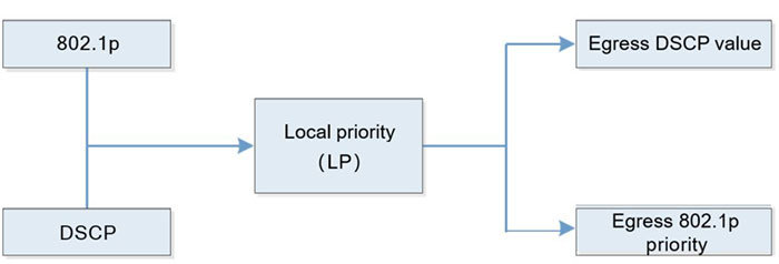
Figure 1-1 Diagram of priority mapping relation
Flow Classification
Flow classification adopts some rule to identify the packets that comply with one feature, divides the packets of different features to multiple classes, and then uses the corresponding QoS mechanism to provide different services for different classes. Therefore, the flow classification is the premise and basis of providing different services.
Flow classification includes counter, meter, flow mirror, re-direction and re-remarking.
Counter and meter perform the counting and metering actions according to the result of the flow classification.
Flow mirror means to mirror the matched packets to the specified ports.
Re-direction means to re-direct the matched packets to the specified port or the specified next hop.
Re-marking means to set or modify the attributes of one kind of packets. After dividing the packets to different kinds via the flow classification, re-marking can modify the attributes of the packet. Prepare for the subsequent processing of the packet.
Traffic Monitoring
Traffic monitoring limits the speed of the ingress packets via the token bucket. To ensure that the overload does not happen to the traffic passing the network and causes the congestion, the device provides the rate limitation based on the port receiving direction, limiting the total rate at the receiving direction of the port. The speeding traffic is dropped.
Traffic Shaping
The typical function of the traffic shaping means to limit the traffic of flowing out from one network, making the packets sent with an average rate. Usually, it is divided to the port traffic shaping and queue traffic shaping. When the sending rate of the packets exceeds the shaping rate, the speeding packets are buffered in the queue and then are sent out with an average rate. The difference between the traffic shaping and traffic monitoring: When using the traffic monitoring to control the packet traffic, the speeding packets are not buffered, but are directly dropped, while the traffic shaping buffers the speeding packets, reducing the dropped packets caused by the burst traffic. However, the traffic shaping may increase the delay, while the traffic monitoring nearly does not increase the delay.
Congestion Management
When the device traffic load is light, do not generate the congestion and the packets are forwarded out when reaching the port. When the arriving rate of the packets is larger than the sending rate of the port and exceeds the processing limit of the port or the device resources are not enough, congestion happens to the device. The congestion may make the communication of the whole network become unreliable. The end-to-end delay, jitter and packet loss rate used to measure the network service quality all increase. If enabling the congestion management and when the congestion happens, the packets queue at the port and waits for the port to forward. The congestion management usually adopts the queue technology and the port determines which queue the packet should be placed according to the packet priority and queue mechanism and how to schedule and forward packets.
The common scheduling includes SP (Strict Priority), RR (Round Robin), WRR (Weighted Round Robin), and WDRR (Weighted Deficit Round Robin).
SP (Strict Priority): There are eight queues on the port, queue 0-7. Queue 7 has the highest priority and queue 0 has the lowest priority.
RR (Round Robin): After one queue schedules one packet, turn to the next queue.
WRR (Weighted Round Robin): It is the weighted scheduling based on packet. You can configure the number of the packets scheduled by each queue before turning to the next queue.
WDRR (Weighted Deficit Round Robin): It is the improvement for the WRR algorithm. The algorithm is based on two variables, that is, quantum and credit counter. The quantum means the weight in the unit of byte and it is a configurable parameter. The credit counter means the accumulation and consumption of the quantum, which is a status parameter and cannot be configured. In the initial state, the credit counter of each queue is equal to the quantum. Every time the queue sends a packet, subtract the byte number of the packet from the credit counter. When the credit counter is lower than 0, stop the scheduling of the queue. When all queues stop scheduling, supplement quantum for all queues.
Congestion Avoidance
The congestion avoidance technology monitors the communication load of the network, so as to avoid the congestion before the network congestion happens. The common used technology is WRED (Weighted Random Early Detection). The difference with the tail drop method is that WRED selects the dropped packet according to the DSCP or IP priority and can provide different performance features for different service types of data. It also can avoid the TCP global synchronization.
In the WRED algorithm, the start point of the queue drop packet is marked as DropStartPoint and the end point of the drop is marked as DropEndPoint. When the average length of the queue is between DropStartPoint and DropEndPoint, WRED drops the packet at random by the corresponding drop rate, while when the queue length exceeds DropEndPoint, drop the packet by 100%. When the queue length is smaller than DropStartPoint, WRED does not drop the packet.
The following is the diagram of the WRED:
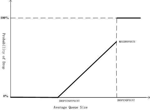
Figure 1-2 WRED diagram
Action Group Function
To support the flow classification and traffic control, the device extends the traditional ACL so that ACL and ACL rule can be bound with one action group respectively, adopting the corresponding action for the matched packet. The action group contains the configurations of the counter, meter, flow mirror, re-direction and re-marking.
For various ACLs and ACL rules being used in different function domains, the configurations of the action groups are different. For the ingress ACL, the used action group of IP ACL is L3 action group and the used action group of MAC ACL is L2 action group. The egress action group is used at the egress direction of ACL. The VFP action group is used to realize the flow-based QinQ. Each ACL can be bound with various action groups, but the effective one depends on the function domain bound with the ACL. For example, one rule of IP ACL is configured with L3 action group, egress action group and VFP action group at the same time. When the IP ACL is applied at the ingress direction, the action in the L3 action group take effect and the actions in the other two action groups do not take effect.
The policy route in the action group is one packet forwarding mechanism for flexible routing based on the destination network. The policy route classifies the packets via Content Aware Processor and forwards the data flow that complies with the classification rule according to the specified next hop. When some packet is routed by other path, but not the shortest path, we can enable the policy route. The priority of the policy route is higher than any other route. Therefore, once the user configures enabling the policy route, the packet sending is processed according to the policy route. Only when the access list matching fails, we can continue to forward according to the searching result of the forwarding table. Otherwise, forward the packet according to the specified next-hop information of the route policy. The specified next hop of the policy route should be the direct-connected next hop. For the non-direct-connected next-hop address, the system permits to configure, but in fact, it is invalid.
 Switch


