Network Requirements
- PC1 and PC2 are two hosts in Sub-VLAN2, PC3 is a host in Sub-VLAN3, and Server is a server in VLAN5.
- The super-VLAN function has been configured on Device. Then, PC1 and PC2 can intercommunicate with each other at layer2. PC1 and PC2 can intercommunicate with PC3 at layer3, and they can access the server.
Network Topology
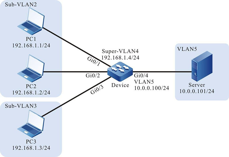
Figure 5-1 Networking for Configuring a Super-VLAN
Configuration Steps
Step 1: On Device, configure VLANs, and configure the port link types of the ports.
#On Device, create VLAN2, VLAN3, VLAN5.
|
Device#configure terminal
Device(config)#vlan 2-3,5
|
#On Device, set the IP address of VLAN interface 4 to 192.168.1.4 and the mask as 255.255.255.0, and set the IP address of VLAN interface 5 to 10.0.0.100 and the mask as 255.255.255.0.
Device(config)#interface vlan 4
Device(config-if-vlan4)#ip address 192.168.1.4 255.255.255.0
Device(config-if-vlan4)#exit
Device(config)#interface vlan 5
Device(config-if-vlan5)#ip address 10.0.0.100 255.255.255.0
Device(config-if-vlan5)#exit
|
#On Device, configure the link type of ports gigabitethernet0/1 and gigabitethernet0/2 to Access and allow services of VLAN2 to pass.
|
Device(config)#interface gigabitethernet 0/1,0/2
Device(config-if-range)#switchport mode access
Device(config-if-range)#switchport access vlan 2
Device(config-if-range)#exit
|
#On Device, configure the link type of port gigabitethernet0/3 to Access and allow services of VLAN3 to pass.
|
Device(config)#interface gigabitethernet 0/3
Device(config-if-gigabitethernet0/3)#switchport mode access
Device(config-if-gigabitethernet0/3)#switchport access vlan 3
Device(config-if-gigabitethernet0/3)#exit
|
#On Device, configure the link type of port gigabitethernet0/4 to Access and allow services of VLAN5 to pass.
|
Device(config)#interface gigabitethernet 0/4
Device(config-if-gigabitethernet0/4)#switchport mode access
Device(config-if-gigabitethernet0/4)#switchport access vlan 5
Device(config-if-gigabitethernet0/4)#exit
|
#Query the VLAN and port information of Device.
Device#show vlan 2
---  ----  ---------------------------  --------  ------------  -------------------------
NO.  VID   VLAN-Name                    Owner     Mode          Interface
---  ----  ---------------------------  --------  ------------  -------------------------
1    2     VLAN0002                     static    Untagged      gi0/1  gi0/2
Device#show vlan 3
---  ----  ---------------------------  --------  ------------  -------------------------
NO.  VID   VLAN-Name                    Owner     Mode          Interface
---  ----  ---------------------------  --------  ------------  -------------------------
1    3     VLAN0003                     static    Untagged      gi0/3
Device#show vlan 5
---  ----  ---------------------------  --------  ------------  -------------------------
NO.  VID   VLAN-Name                    Owner     Mode          Interface
---  ----  ---------------------------  --------  ------------  -------------------------
1    5     VLAN0005                     static    Untagged      gi0/4
Step 2: On Device, configure the super-VLAN function.
#On Device, configure VLAN4 as the super-VLAN, VLAN2 and VLAN3 as sub-VLANs, and enable ARP proxy.
|
Device(config)#super-vlan 4
Device(config-super-vlan4)#sub-vlan 2,3
Device(config-super-vlan4)#arp proxy enable
Device(config-super-vlan4)#exit
|
#Query the super-VLAN information of Device.
Device#show super-vlan
------------------------------------------------------------------------
NO. SuperVlan   Description                     Arp Proxy SubVlan Member
------------------------------------------------------------------------
1    4          SuperVLAN0004                    enable    2-3

-
To enable the hosts in different sub-VLANs to communicate with each other at layer 3, the ARP proxy function must be enabled.
- Super-VLAN and Sub-VLAN should be in one spanning tree instance.
Step 3: Check the result. Use the ping command to check the connectivity between PC1, PC2, PC3 and the server.
#PC1 and PC2 in Sub-VLAN2 can ping each other successfully.
#PC1 and PC2 in Sub-VLAN2 and PC3 in Sub-VLAN3 can ping each other successfully.
#PC1, PC2, and PC3 in Sub-VLANs and the server can ping each other successfully.
 Switch


