Network Requirements
- Four devices form the dual-uplink networking. The uplink devices are Device1, Device2, and Device3; the downlink device is Device4.
- Configure the ULPP function on the downlink device so that the port normally bears or switches the services in the associated spanning tree instance.
Network Topology
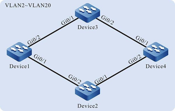
Figure 4-1 Networking of configuring the ULPP group
Configuration Steps
Step 1: Configure the link type of the VLAN and port.
#Create VLAN2-VLAN20 on Device1, configure the link type of port gigabiteternet0/1, gigabiteternet0/2 on Device1 as Trunk; permit the services of VLAN2-VLAN20 to pass.
|
Device1#configure terminal
Device1(config)#vlan 2-20
Device1(config)#interface gigabitethernet 0/1
Device1(config-if-gigabitethernet0/1)#switchport mode trunk
Device1(config-if-gigabitethernet0/1)#switchport trunk allowed vlan add 2-20
Device1(config-if-gigabitethernet0/1)#exit
Device1(config)#interface gigabitethernet 0/2
Device1(config-if-gigabitethernet0/2)#switchport mode trunk
Device1(config-if-gigabitethernet0/2)#switchport trunk allowed vlan add 2-20
Device1(config-if-gigabitethernet0/2)#exit
|

-
The configuration of the VLAN, port and link type of Device2, Device3, and Device4 is the same as that of Device1. (Omitted)
Step 2: Configure the spanning tree instance on Device4.
#Configure the spanning tree instance; instance 1 maps VLAN3-VLAN10; instance 2 maps VLAN11-VLAN20.
|
Device4(config)#spanning-tree mst configuration
Device4(config-mst)#region-name admin
Device4(config-mst)#revision-level 1
Device4(config-mst)#instance 1 vlan 3-10
Device4(config-mst)#instance 2 vlan 11-20
|
#Enable the spanning tree instance.
|
Device4(config-mst)#active configuration pending
Device4(config-mst)#exit
|
Step 3: Configure the ULPP function on Device4.
#Create the ULPP group.
|
Device4(config)#ulpp-group 1
|
#Configure the master port gigabitethernet0/1 and slave port gigabitethernet0/2 of the ULPP group.
|
Device4(config-ulpp-1)#master interface gigabitethernet 0/1
Device4(config-ulpp-1)#slave interface gigabitethernet 0/2
|
#Configure the master port gigabitethernet0/1 to link with the spanning tree instance 1 and slave port gigabitethernet0/2 to link with the spanning tree instance 2.
|
Device4(config-ulpp-1)#instance group 1 master
Device4(config-ulpp-1)#instance group 2 slave
|
#Configure the work mode of the ULPP group as the link backup.
|
Device4(config-ulpp-1)#mode backup
|
#Configure the control VLAN of the ULPP group as VLAN2.
|
Device4(config-ulpp-1)#control-vlan 2
|
#Enable the sending mechanism of the ULPP Flush packet.
|
Device4(config-ulpp-1)#flush enable
|
#Enable the ULPP group.
|
Device4(config-ulpp-1)#enable
Device4(config-ulpp-1)#exit
|
-
After VLAN2 is configured as control VLAN, only the Flush packets can pass in the VLAN, but the other service packets cannot.
Step 4: Configure the uplink device Device1, Device2 and Device3.
#Configure the receiving and sending mechanism of the Flush packets on Device1.
|
Device1(config)#interface gigabitethernet 0/1-0/2
Device1(config-if-range)#ulpp flush control-vlan 2
Device1(config-if-range)#exit
|
-
The receiving and forwarding mechanism of Device2 and Device3 is the same as that of Device1. (Omitted)
Step 5: Check the result.
#View the ULPP group status on Device4.
Device4#show ulpp group 1
--------------------------
ulpp-group 1 configuration information
---------------------------
Current status             : MASS
Work type                  : Backup
Control vlan                2
Flush function             : Enable
Preemtion mode             : Disable
Master interface name      : gi0/1
Slave interface name       : gi0/2
Master interface status    : Active
Slave interface status	   : Standby
Master interface instance   1
Slave interface instance	2
Flexlink compatible        : Disable
Smartlink compatible	   : Disable
Smartlink mcast compatible : Disable
Enable status		       : Enable
#View the status of the associated spanning tree instance of the master and slave port on Device4.
Device4#show ulpp instance group 1
-----------------------------------
ulpp-group 1 instance status
-----------------------------------
Master forwarding instance   : 1-2
Master block instance		 : None
Slave forwarding instance    : None
Slave block instance         : 1-2
#After port gigabitethernet0/1 of Device4 fails, switch over the status of the ULPP group. View the status of the ULPP group on Device4.
Device4#show ulpp group 1
--------------------------------
ulpp-group 1 configuration information
--------------------------------
Current status             : MNSA
Work type                  : Backup
Control vlan                2
Flush function             : Enable
Preemtion mode             : Disable
Master interface name      : gi0/1
Slave interface name       : gi0/2
Master interface status    : Down
Slave interface status     : Active
Master interface instance	1
Slave interface instance	2
Flexlink compatible        : Disable
Smartlink compatible       : Disable
Smartlink mcast compatible : Disable
Enable status              : Enable
The master port gigabitethernet0/1 changes from Active to Down; the slave port gigabitethernet0/2 changes from Standby to Active; the services in the spanning tree instance are forwarded normally via gigabitethernet0/2.
#The uplink device Device1 and Device2 prints the following information.
19:26:10: [tUlpp]%ULPP-ASSI: Receive flush message from gigabitethernet0/2 success, the receive sequence number is 1, vlan id is 2
The printed is the information of the Flush packet received by the uplink device Device1 and Device2 when the status of the ULPP group switches.
 Switch


