Network Requirements
- Set up EBGP neighbors between Device1 and Device2 and between Device1 and Device3, and set up IBGP neighbors between Device2 and Device3.
- Device1 learns EBGP route 3.0.0.0/24 both from Device2 and Device3, and Device1 selects to forward data to the network segment 3.0.0.0/24 through Device2.
- On Device1 and Device2, configure EBGP to coordinate with BFD. When the line between Device1 and Device2 becomes faulty, BFD can quickly detect the fault and notify BGP of the fault. Then Device1 selects to forward data to network segment 3.0.0.0/24 through Device3.
Network Topology
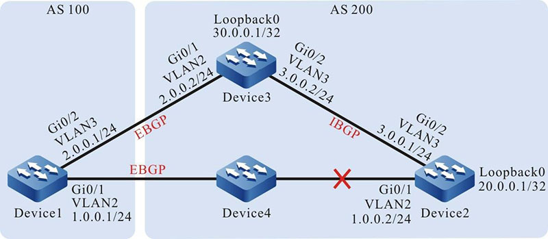
Figure 12–8 Networking for configuring BGP to coordinate with BFD
Configuration Steps
Step 1: Configure the VLAN and join the interface to the corresponding VLAN. (Omitted)
Step 2: Configure the IP addresses of the interfaces. (Omitted)
Step 3: Configure OSPF so that loopback routes are reachable between devices.
#Configure Device2.
|
Device2#configure terminal
Device2(config)#router ospf 100
Device2(config-ospf)#network 3.0.0.0 0.0.0.255 area 0
Device2(config-ospf)#network 20.0.0.1 0.0.0.0 area 0
Device2(config-ospf)#exit
|
#Configure Device3.
|
Device3#configure terminal
Device3(config)#router ospf 100
Device3(config-ospf)#network 3.0.0.0 0.0.0.255 area 0
Device3(config-ospf)#network 30.0.0.1 0.0.0.0 area 0
Device3(config-ospf)#exit
|
#Query the routing table of Device2.
Device2#show ip route ospf
Codes: C - Connected, L - Local, S - static, R - RIP, B - BGP, i-ISIS
       U - Per-user Static route
       O - OSPF, OE-OSPF External, M - Management, E - IRMP, EX - IRMP external

O	30.0.0.1/32 [110/2] via 3.0.0.2, 00:02:26, vlan3
#Query the routing table of Device3.
Device3#show ip route ospf
Codes: C - Connected, L - Local, S - static, R - RIP, B BGP, i-ISIS
       U Per-user Static route
       O - OSPF, OE-OSPF External, M - Management, E - IRMP, EX IRMP external

O 20.0.0.1/32 [110/2] via 3.0.0.1, 00:03:38, vlan3
According to the routing table, Device2 and Device3 have learnt the routes of the loopback interfaces of each other.
Step 4: Configure an ACL and routing policy to set metric of a route.
#Configure Device1.
|
Device1#configure terminal
Device1(config)#ip access-list standard 1
Device1(config-std-nacl)#permit 3.0.0.0 0.0.0.255
Device1(config-std-nacl)#commit
Device1(config-std-nacl)#exit
Device1(config)#route-map SetMetric
Device1(config-route-map)#match ip address 1
Device1(config-route-map)#set metric 50
Device1(config-route-map)#exit
|
The routing policy that is configured on Device1 sets the metric of route 3.0.0.0/24 to 50.
Step 5 Configure BGP, and configure Device1 with a routing policy.
#Configure Device1.
|
Device1(config)#router bgp 100
Device1(config-bgp)#neighbor 1.0.0.2 remote-as 200
Device1(config-bgp)#neighbor 2.0.0.2 remote-as 200
Device1(config-bgp)#neighbor 2.0.0.2 route-map SetMetric in
Device1(config-bgp)#exit
|
#Configure Device2.
|
Device2(config)#router bgp 200
Device2(config-bgp)#neighbor 1.0.0.1 remote-as 100
Device2(config-bgp)#neighbor 30.0.0.1 remote-as 200
Device2(config-bgp)#neighbor 30.0.0.1 update-source loopback0
Device2(config-bgp)#network 3.0.0.0 255.255.255.0
Device2(config-bgp)#exit
|
#Configure Device3.
|
Device3(config)#router bgp 200
Device3(config-bgp)#neighbor 2.0.0.1 remote-as 100
Device3(config-bgp)#neighbor 20.0.0.1 remote-as 200
Device3(config-bgp)#neighbor 20.0.0.1 update-source loopback0
Device3(config-bgp)#network 3.0.0.0 255.255.255.0
Device3(config-bgp)#exit
|
After a routing policy is configured on the peer, the BGP must be reset to make the configuration take effect.
#On Device1, check the BGP neighbor status.
Device1#show ip bgp summary
BGP router identifier 2.0.0.1, local AS number 100 BGP table version is 2
2 BGP AS-PATH entries 0 BGP community entries

Neighbor    V AS        MsgRcvd MsgSent TblVer InQ OutQ Up/Down    State/PfxRcd
1.0.0.2      4  200      2            2            2        0     0      00:01:32       1
2.0.0.2      4  200      2            2            2        0     0      00:01:43       1
#On Device2, check the BGP neighbor status.
Device2#show ip bgp summary
BGP router identifier 20.0.0.1, local AS number 200 BGP table version is 2
1 BGP AS-PATH entries 0 BGP community entries

Neighbor    V  AS     MsgRcvd MsgSent TblVer InQ OutQ Up/Down State/PfxRcd
1.0.0.1       4  100   2            2            2        0    0       00:02:52       0
30.0.0.1     4  200   3             3           2        0    0       00:02:45       1
BGP neighbors between Device1, Device2, and Device3 have been set up successfully.
#Query the routing table of Device1.
Device1#show ip bgp
BGP table version is 3, local router ID is 1.0.0.1
Status codes: s suppressed, d damped, h history, * valid, > best, i - internal,
              S Stale
Origin codes: i - IGP, e - EGP, ? - incomplete
         Network        Next Hop     Metric  LocPrf Weight Path
[B]*   3.0.0.0/24	2.0.0.2         50       0                   200 i
[B]*>                   1.0.0.2         0         0                   200 i

Device1#show ip route bgp
Codes: C - Connected, L - Local, S - static, R - RIP, B BGP, i-ISIS
       U Per-user Static route
       O - OSPF, OE-OSPF External, M - Management, E - IRMP, EX IRMP external

B 3.0.0.0/24 [20/0] via 1.0.0.2, 00:07:19, vlan2
According to the routing table, route 3.0.0.0/24 of Device1 selects Device2 as the next-hop device.
Step 6: Configure BGP to coordinate with BFD.
#Configure Device1.
|
Device1(config)#bfd fast-detect
Device1(config)#router bgp 100
Device1(config-bgp)#neighbor 1.0.0.2 fall-over bfd
Device1(config-bgp)#exit
Device1(config)#interface vlan2
Device1(config-if-vlan2)#bfd min-receive-interval 500
Device1(config-if-vlan2)#bfd min-transmit-interval 500
Device1(config-if-vlan2)#bfd multiplier 4
Device1(config-if-vlan2)#exit
|
#Configure Device2.
|
Device2(config)#bfd fast-detect
Device2(config)#router bgp 200
Device2(config-bgp)#neighbor 1.0.0.1 fall-over bfd
Device2(config-bgp)#exit
Device2(config)#interface vlan2
Device2(config-if-vlan2)#bfd min-receive-interval 500
Device2(config-if-vlan20)#bfd min-transmit-interval 500
Device2(config-if-vlan2)#bfd multiplier 4
Device2(config-if-vlan2)#exit
|
BFD is enabled between EBGP neighbors Device1 and Device2, and the minimum transmit interval, minimum receive interval, and detection timeout multiple of the BFD control packets have been modified.
Step 7: Check the result.
#On Device1, query the BFD session status.
Device1#show bfd session
OurAddr   NeighAddr    LD/RD    State Holddown   interface
1.0.0.1	   1.0.0.2        2/2         UP     2000         vlan2
On Device1, the BFD status is up, and the holddown time is negotiated to be 2000ms.
#If the line between Device1 and Device2 becomes faulty, the route can quickly switch over to the backup line.
#Query the routing table of Device1.
Device1#show ip bgp
BGP table version is 6, local router ID is 1.0.0.1
Status codes: s suppressed, d damped, h history, * valid, > best, i internal,
              S Stale
Origin codes: i - IGP, e - EGP, ? incomplete
         Network         Next Hop    Metric LocPrf Weight Path
[B]*> 3.0.0.0/24     2.0.0.2       50      0                   200 i

Device1#show ip route bgp
Codes: C - Connected, L - Local, S - static, R - RIP, B BGP, i-ISIS
       U Per-user Static route
       O - OSPF, OE-OSPF External, M - Management, E - IRMP, EX IRMP external

B 3.0.0.0/24 [20/50] via 2.0.0.2, 00:00:05, vlan3
The next hop of route 3.0.0.0/24 is Device3.
 Switch


