Network Requirement
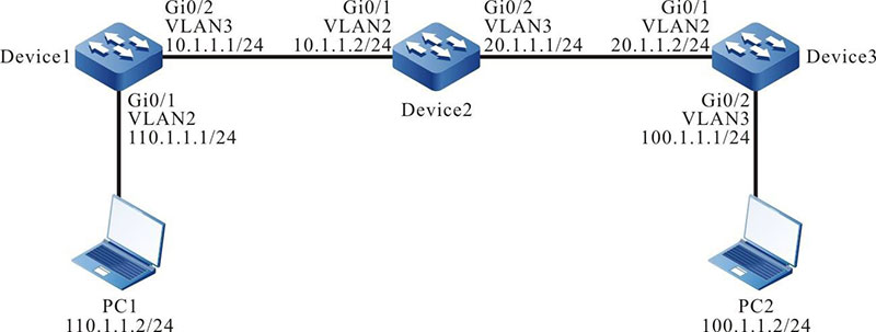
- On Device1, Device2 and Device3, configure static routes so that PC1 and PC2 can communicate with each other.
Network Topology

Figure 3-1 Networking for Configure Static Routing Basic Functions
Configuration Steps
Step 1: Create VLANs, and add ports to the required VLANs. (Omitted)
Step 2: Configure IP addresses for the ports. (Omitted)
Step 3: Configure static routes.
#Configure Device1.
|
Device1#configure terminal
Device1(config)#ip route 20.1.1.0 255.255.255.0 10.1.1.2
Device1(config)#ip route 100.1.1.0 255.255.255.0 10.1.1.2
|
#Configure Device2.
|
Device2#configure terminal
Device2(config)#ip route 110.1.1.0 255.255.255.0 10.1.1.1
Device2(config)#ip route 100.1.1.0 255.255.255.0 20.1.1.2
|
#Configure Device3.
|
Device3#configure terminal
Device3(config)#ip route 0.0.0.0 0.0.0.0 20.1.1.1
|
#Query the routing table of Device1.
Device1#show ip route
Codes: C - connected, S - static, R - RIP, O - OSPF, OE-OSPF External, M - Management
       D - Redirect, E - IRMP, EX - IRMP external, o - SNSP, B - BGP, i-ISIS

Gateway of last resort is not set

C	10.1.1.0/24 is directly connected, 00:06:47, vlan3
S   20.1.1.0/24 [1/100] via 10.1.1.2, 00:00:13, vlan3
S   100.1.1.0/24 [1/100] via 10.1.1.2, 00:00:05, vlan3
C   110.1.1.0/24 is directly connected, 00:08:21, vlan2
C   127.0.0.0/8 is directly connected, 28:48:33, lo0
#Query the routing table of Device2.
Device2#show ip route
Codes: C - connected, S - static, R - RIP, O - OSPF, OE-OSPF External, M Management
       D - Redirect, E - IRMP, EX - IRMP external, o - SNSP, B BGP, i-ISIS

Gateway of last resort is not set

C 10.1.1.0/24 is directly connected, 00:00:37, vlan2
C 20.1.1.0/24 is directly connected, 00:00:27, vlan3
S 100.1.1.0/24 [1/100] via 20.1.1.2, 00:00:05, vlan3
S 110.1.1.0/24 [1/100] via 10.1.1.1, 00:00:13, vlan2
C 127.0.0.0/8 is directly connected, 30:13:18, lo0
Query the routing table of Device3.
Device3#show ip route
Codes: C - connected, S - static, R - RIP, O - OSPF, OE-OSPF External, M Management
       D - Redirect, E - IRMP, EX - IRMP external, o - SNSP, B BGP, i-ISIS

Gateway of last resort is 20.1.1.2 to network 0.0.0.0

S 0.0.0.0/0 [1/100] via 20.1.1.1, 00:00:07, vlan2
C   20.1.1.0/24 is directly connected, 00:00:08, vlan2
C   100.1.1.0/24 is directly connected, 00:00:13, vlan3
C   127.0.0.0/8 is directly connected, 29:17:19, lo0
Step 4: Check the result. Use the ping command to verify the connectivity between PC1 and PC2
#On PC1, use the ping command to check the connectivity.
C:\Documents and Settings\Administrator>ping 100.1.1.2

Pinging 100.1.1.2 with 32 bytes of data:

Reply from 100.1.1.2: bytes=32 time<1ms TTL=125
Reply from 100.1.1.2: bytes=32 time<1ms TTL=125
Reply from 100.1.1.2: bytes=32 time<1ms TTL=125
Reply from 100.1.1.2: bytes=32 time<1ms TTL=125

Ping statistics for 100.1.1.2:
    Packets: Sent = 4, Received = 4, Lost = 0 (0% loss), Approximate round trip times in milli-seconds:
    Minimum = 0ms, Maximum = 0ms, Average = 0ms
PC1 and PC2 can communicate with each other.
 Switch
 Wifi - Access Point
 Firewall
 Router
 Module Quang
![Module Quang Cisco]() Module Quang Cisco
Module Quang Cisco![Module quang HPE]() Module quang HPE
Module quang HPE![Module quang Maipu]() Module quang Maipu
Module quang Maipu![Module quang Brocade]() Module quang Brocade
Module quang Brocade![Module quang Fortinet]() Module quang Fortinet
Module quang Fortinet![Module quang Aruba]() Module quang Aruba
Module quang Aruba![Module quang OEM]() Module quang OEM
Module quang OEM![Module quang Juniper]() Module quang Juniper
Module quang Juniper![Module quang Dell]() Module quang Dell
Module quang Dell![Module quang Palo Alto]() Module quang Palo Alto
Module quang Palo Alto![Module quang Huawei]() Module quang Huawei
Module quang Huawei![Module quang Arista]() Module quang Arista
Module quang Arista![Module quang F5]() Module quang F5
Module quang F5![Module quang H3C]() Module quang H3C
Module quang H3C![Module Quang Allied Telesis]() Module Quang Allied Telesis
Module Quang Allied Telesis![Module quang SonicWall]() Module quang SonicWall
Module quang SonicWall![Module quang Mikrotik]() Module quang Mikrotik
Module quang Mikrotik![Module quang Handar]() Module quang Handar
Module quang Handar Máy chủ (Server)
 Thiết bị lưu trữ (SAN, NAS)
 Load Balancing
 Video Conferencing
 Phụ kiện máy chủ
 Thiết Bị IoT
 Phụ Kiện Mạng


.png)


