Network Requirements
- On Device1, configure multicast routing protocol.
- On Device2, enable IGMP snooping and GMP snooping proxy, and configure IGMP snooping static group.
- Multicast Server sends the multicast service packet; PC1, PC2, and PC3 can correctly receive the multicast service packet.
Network Topology
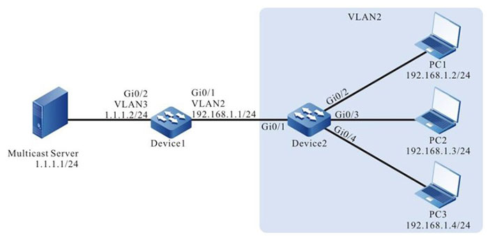
Figure 2-3 Network topology of configuring IGMP snooping proxy
Configuration Steps
Step 1: Device1 configures the interface IP address and enables the multicast route protocol.
|
Device1# ip pim sparse-mode
Device1(config-if-vlan2)# exit
Device1(config)#interface vlan 3
Device1(config-if-vlan3)# ip address 1.1.1.2 255.255.255.0
Device1(config-if-vlan3)# ip pim sparse-mode
Device1(config-if-vlan3)# exit
|
Step 2: Configure Device2.
#Create VLAN2 on Device2.
|
Device2#configure terminal
Device2(config)#vlan 2
Device2(config-vlan2)#exit
|
#Configure the link type of the port gigabitethernet0/2-gigabitethernet0/4 on Device2 as Access, permitting the services of VLAN2 to pass.
|
Device2(config)#interface gigabitethernet 0/2-0/4
Device2(config-if-range)#switchport access vlan 2
Device2(config-if-range)#exit
|
#Configure the link type of port gigabitethernet0/1 on Device2 as Trunk, permitting the services of VLAN2 to pass; PVID is configured as 1.
|
Device2(config)#interface gigabitethernet 0/1
Device2(config-if-gigabitethernet0/1)#switchport mode trunk
Device2(config-if-gigabitethernet0/1)#switchport trunk allowed vlan add 2
Device2(config-if-gigabitethernet0/1)#switchport trunk pvid vlan 1
Device2(config-if-gigabitethernet0/1)#exit
|
#Enable IGMP snooping in VLAN2; configure IGMP snooping querier address as 192.168.1.254.
|
Device2(config)#ip igmp snooping
Device2(config)#ip igmp snooping vlan 2
Device2(config)#ip igmp snooping vlan 2 querier
Device2(config)#ip igmp snooping vlan 2 querier address 192.168.1.254
|
#Configure IGMP snooping proxy.
|
Device2(config)#ip igmp snooping proxy vlan 2 upstream interface gigabitethernet 0/1
|
#Configure IGMP snooping static group.
|
Device2(config)#ip igmp snooping vlan 2 static-group 224.1.1.1 interface gigabitethernet 0/4
Device2(config)#exit
|
Step 3: Check the result.
#IGMP snooping is added to group dynamically: PC1, PC2 and PC3 successively sends IGMPv2 member report packets to add to multicast group 224.1.1.1.
#View the IGMP snooping proxy information of Device2.
Device2#show ip igmp proxy upstream vlan 2
vlan 2 proxy upstream information:
----------------------------------------------------
upstream interface                      : gi0/1
upstream querier compatmode version     : 2
upstream querier address                : 192.168.1.1
upstream report source address          : 192.168.1.4
upstream querier query interval         : 125s
upstream querier query response interval: 10s
upstream querier LMQI                   :   1s
upstream querier LMQC                   : 2
upstream querier robustness variable    : 2
upstream querier present timer          : 00:02:50
upstream V1 querier present timer       : stopped
upstream V2 querier present timer       : 00:02:55
#View multicast member table of Device2 and IGMP snooping proxy member database.
Device2#show ip igmp snooping groups
IGMP Snooping Group Membership
Total 2 groups

VLAN ID Interface Name Group Address Expires   Last Reporter V1 Expires V2 Expires Uptime
----------------------------------------------------------------------------------------
2       gi0/2          224.1.1.1     00:04:09  192.168.1.2   stopped               00:00:14
2       gi0/3          224.1.1.1     00:04:09  192.168.1.3   stopped               00:00:11

IGMP Snooping Static Group Membership
Total 1 group

VLAN ID  Port Name   Group Address  Uptime
-------  ----------  -------------  --------
2        gi0/4       224.1.1.1      00:00:48
You can see that PC1, PC2 and PC3 add to multicast group 224.1.1.1.
Device2#show ip igmp snooping proxy member database vlan 2
IGMP Snooping Proxy Member Database Table
Total 1 group

VLAN ID Group Address   Mode     Source Address
------  --------------  ------   --------------
2       224.1.1.1       EXCLUDE  *
#View multicast member table of Device1.
Device1#show ip igmp groups
IGMP Connected Group Membership
Total 1 groups
Group Address  Interface   Uptime     Expires   Last Reporter   V1 Expires V2 Expires
-------------------------------------------------------------------------------------
224.1.1.1      vlan 2      00:00:15   00:04:11  192.168.1.254   stopped
You can see that when PC adds to multicast group 224.1.1.1, Device2 can only forward the first IGMPv2 member report packet to Device1 and the other are all dropped. The source IP address of the member report packet is the configured querier address of Device2.
#Multicast Server sends the multicast service packet with destination address 224.1.1.1; PC1, PC2 and PC3 can correctly receive the multicast service packet.
#PC1 sends IGMPv2 leave packet to leave multicast group 224.1.1.1.
Device2#show ip igmp snooping groups
IGMP Snooping Group Membership
Total 1 group

VLAN ID Interface Name Group Address Expires  Last Reporter V1 Expires V2 Expires Uptime
------------------------------------------------------------------------------------------
2       gi0/3          224.1.1.1     00:03:54 192.168.1.3   stopped               00:06:37

IGMP Snooping Static Group Membership
Total 1 group

VLAN ID Port Name   Group Address  Uptime
------- ----------  -------------  -------
2       gi0/4       224.1.1.1      00:00:48

Device1#show ip igmp groups
IGMP Connected Group Membership
Total 1 groups

Group Address  Interface   Uptime    Expires Last  Reporter       V1 Expires V2 Expires
---------------------------------------------------------------------------------------
224.1.1.1      vlan 2      00:06:48  00:03:48      192.168.1.254  stopped
After PC1 leaves multicast group 224.1.1.1, PC2 does not leave the multicast group, and the direct-connected port of PC3 is the member port of IGMP snooping static group 224.1.1.1, there are still group members PC2 and PC3 in the multicast member table. Therefore, Device2 does not send the leave packet of the multicast group to Device1.
#PC1 cannot receive the multicast service packet, but PC2 and PC3 can correctly receive the multicast service packets.
#PC2 sends the IGMPv2 leave packet to leave multicast group 224.1.1.1; view multicast member table of Device2 and Device1.
Device2#show ip igmp snooping groups
IGMP Snooping Static Group Membership
Total 1 group

VLAN ID  Port Name   Group Address  Uptime
-------  ---------   -------------  --------
2        gi0/4       224.1.1.1      00:00:48

Device1#show ip igmp groups
IGMP Connected Group Membership
Total 1 groups
Group Address  Interface    Uptime    Expires  Last Reporter   V1 Expires V2 Expires
------------------------------------------------------------------------------------
224.1.1.1      vlan 2       00:07:08  00:03:28 192.168.1.254   stopped
When PC2 leaves the multicast group 224.1.1.1, because the direct-connected port of PC3 is the member port of IGMP snooping static group 224.1.1.1, there is still group member PC3 in the multicast member table, so Device2 will not send the leave message of the multicast group to Device1.
#PC1 and PC2 cannot receive multicast service packets, PC3 can receive multicast service packet correctly.
#Delete the configured IGMP snooping static group and view the multicast member tables of Device1 and Device2.
|
Device2#show ip igmp snooping groups
|
You can see that there is no multicast member table on Device2.
|
Device1#show ip igmp groups
|
There is no multicast member on Device1. When the last group member PC3 leaves the multicast group, Device2 sends the leave packet of the multicast group to Device1.
#PC1, PC2 and PC3 cannot receive the multicast service packet.
 Switch


