Network Requirements
Network Topology
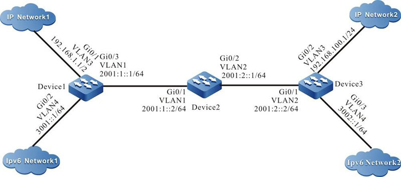
Figure 12-1 Networking for Configuring the basic functions of IPv6 tunnel
Configuration Steps
Step 1: Configure the IP address of the interface (omitted).
Step 2: Configure OSPFv3, making Device1, Device2, and Device3 communicate with each other.
#Configure Device1.
|
Device1#configure terminal
Device1(config)#ipv6 router ospf 100
Device1(config-ospf6)#router-id 1.1.75.1
Device1(config-ospf6)#exit
Device1(config)#interface vlan1
Device1(config-if-vlan1)#ipv6 router ospf tag 100 area 0
Device1(config-if-vlan1)#exit
|
#Configure Device2.
|
Device2#configure terminal
Device2(config)#ipv6 router ospf 100
Device2(config-ospf6)#router-id 1.2.75.1
Device2(config-ospf6)#exit
Device2(config)#interface vlan1
Device2(config-if-vlan1)#ipv6 router ospf tag 100 area 0
Device2(config-if-vlan1)#exit
Device2(config)#interface vlan2
Device2(config-if-vlan2)#ipv6 router ospf tag 100 area 0
Device2(config-if- vlan2)#exit
|
#Configure Device3.
|
Device3#configure terminal
Device3(config)#ipv6 router ospf 100
Device3(config-ospf6)#router-id 1.1.73.1
Device3(config-ospf6)#exit
Device3(config)#interface vlan2
Device3(config-if-vlan2)#ipv6 router ospf tag 100 area 0
Device3(config-if-vlan2)#exit
|
#Query the IPv6 route table f Device3.
Device3#show ipv6 route
Codes: C - Connected, L - Local, S - static, R - RIP, B - BGP, i-ISIS
       U - Per-user Static route
       O - OSPF, OE-OSPF External, M - Management

L ::1/128 [0/0]
     via ::, 6w0d:23:09:31, lo0
O 2001:1::/64 [110/2]
     via fe80::508b:fff:fee4:ff6, 00:08:37, vlan2
C  2001:2::/64 [0/0]
     via ::, 00:15:51, vlan2
L 2001:2::2/128 [0/0]
     via ::, 00:15:50, lo0
C 3002::/64 [0/0]
     via ::, 00:15:06, vlan4
L 3002::1/128 [0/0]
     via ::, 00:15:04, lo0

- The querying methods of Device1 and Device2 are the same as that of Device3, so the querying process is omitted.
Step 3: Configure the IPv6 tunnel.
#On Device1, configure IPv6 tunnel tunnel1, the source address is 2001:1::1, the destination address is 2001:2::2, IP address is 10.0.0.1, and the IPv6 address is 10::1.
|
Device1(config)#interface tunnel 1
Device1(config-if-tunnel1)#tunnel mode ipipv6
Device1(config-if-tunnel1)#tunnel source 2001:1::1
Device1(config-if-tunnel1)#tunnel destination 2001:2::2
Device1(config-if-tunnel1)#ip address 10.0.0.1 255.255.255.0
Device1(config-if-tunnel1)#ipv6 address 10::1/64
Device1(config-if-tunnel1)#exit
|
#On Device3, configure IPv6 tunnel tunnel1, the source address is 2001:2::2, the destination address is 2001:2::2, IP address is 10.0.0.2, and the IPv6 address is 10::2
|
Device3(config)#interface tunnel 1
Device3(config-if-tunnel1)#tunnel mode ipipv6
Device3(config-if-tunnel1)#tunnel source 2001:2::2
Device3(config-if-tunnel1)#tunnel destination 2001:1::1
Device3(config-if-tunnel1)#ip address 10.0.0.2 255.255.255.0
Device3(config-if-tunnel1)#ipv6 address 10::2/64
Device3(config-if-tunnel1)#exit
|
#Query the IPv6 tunnel information of Device3.
Device3#show tunnel 1 Tunnel 1:
    Tunnel mode is ipipv6
    Source ipv6 address is 2001:2::2(Source ipv6 address is up on source interface vlan2)
    Destination ipv6 address is 2001:1::1
    Tunnel state is up
    Encapsulation vrf is global(0x0)
    TTL(time-to-live) is 255
    TOS(type of service) is not set
total(1)
-
The querying method of Device1is the same as that of Device3, so the querying process is omitted.
- When the tunnel is not in the same network segment, it is necessary to configure the static route to the peer tunnel on the devices at both ends of the tunnel, and the output interface is the tunnel interface.
Step 4: Configure the static route.
#On Device1, configure the static route to IP Network2 with the egress interface tunnel1.
|
Device1(config)#ip route 192.168.100.0 255.255.255.0 tunnel1
|
#On Device3, configure the static route to IP Network1 with the egress interface tunnel1.
|
Device3(config)#ip route 192.168.1.0 255.255.255.0 tunnel1
|
#Query the route table of Device3.
Device3#show ip route
Codes: C - connected, S - static, R - RIP, O - OSPF, OE-OSPF External, M - Management
       D - Redirect, E - IRMP, EX - IRMP external, o - SNSP, B - BGP, i-ISIS

Gateway of last resort is not set

C   10.0.0.0/24 is directly connected, 00:17:12, tunnel1
S 192.168.1.0/24 [1/100000] is directly connected, 00:00:10, tunnel1
C 192.168.100.0/24 is directly connected, 00:00:28, vlan3
-
The querying method of Device1 is the same as that of Device3, so the querying process is omitted.
 Switch


