Network Requirement
- Device1 has the default route and the gateway is Device2.
- Configure the PBR on Device1 to enable PC to visit the network 1.1.1.0/24 via Device3 and visit network 1.1.2.0/24 via Device2.
Network Topology
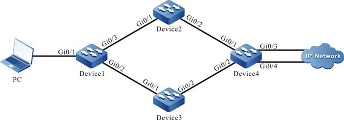
Figure 14-1 Networking of configuring the PBR
|
Device
|
Interface
|
VLAN
|
IP Address
|
|
PC
|
|
|
10.1.1.1/24
|
|
Device1
|
Gi0/1
|
2
|
10.1.1.2/24
|
|
|
Gi0/2
|
3
|
20.1.1.1/24
|
|
|
Gi0/3
|
4
|
30.1.1.1/24
|
|
Device2
|
Gi0/1
|
2
|
30.1.1.2/24
|
|
|
Gi0/2
|
3
|
50.1.1.1/24
|
|
Device3
|
Gi0/1
|
2
|
20.1.1.2/24
|
|
|
Gi0/2
|
3
|
40.1.1.1/24
|
|
Device4
|
Gi0/1
|
2
|
50.1.1.2/24
|
|
|
Gi0/2
|
3
|
40.1.1.2/24
|
|
|
Gi0/3
|
4
|
1.1.1.1/24
|
|
|
Gi0/4
|
5
|
1.1.2.1/24
|
Configuration Steps
Step 1: Configure the VLAN and join the interface to the corresponding VLAN. (Omitted)
Step 2: Configure the IP addresses of the interfaces. (Omitted)
Step 3: Configure the static route.
#Configure Device1.
|
Device1#configure terminal
Device1(config)#ip route 0.0.0.0 0.0.0.0 30.1.1.2
|
#Configure Device2.
|
Device2#configure terminal
Device2(config)#ip route 10.1.1.0 255.255.255.0 30.1.1.1
Device2(config)#ip route 1.1.0.0 255.255.0.0 50.1.1.2
|
#Configure Device3.
|
Device3#configure terminal
Device3(config)#ip route 10.1.1.0 255.255.255.0 20.1.1.1
Device3(config)#ip route 1.1.0.0 255.255.0.0 40.1.1.2
|
#Configure Device4.
|
Device4#configure terminal
Device4(config)#ip route 30.1.1.0 255.255.255.0 50.1.1.1
Device4(config)#ip route 20.1.1.0 255.255.255.0 40.1.1.1
Device4(config)#ip route 10.1.1.0 255.255.255.0 50.1.1.1
Device4(config)#ip route 10.1.1.0 255.255.255.0 40.1.1.1
|
#View the routing table of Device1.
Device1#show ip route
Codes: C - connected, S - static, R - RIP, O - OSPF, OE-OSPF External, M - Management
       D - Redirect, E - IRMP, Ex - IRMP external, o - SNSP, B - BGP, i-ISIS

Gateway of last resort is 30.1.1.2 to network 0.0.0.0

S	0.0.0.0/0 [1/100] via 30.1.1.2, 00:26:24, vlan4
C 10.1.1.0/24 is directly connected, 00:00:59, vlan2
C 20.1.1.0/24 is directly connected, 00:00:50, vlan3
C 30.1.1.0/24 is directly connected, 00:00:39, vlan4
C 127.0.0.0/8 is directly connected, 03:47:36, lo0
Step 4: Configure the PBR on Device1.
#Configure the PBR action group and redirect the packet to the next hop 20.1.1.2.
|
Device1(config)#pbr-action-group pbr
Device1(config-action-group)#redirect ipv4-nexthop 20.1.1.2
Device1(config-action-group)#exit
|
#View the PBR action group information on Device1.
Device1#show pbr-action-group pbr
pbr-action-group pbr
redirect ipv4-nexthop 20.1.1.2(valid)
#Configure the ACL and bind the ACL rule macthing the destination IP network segment 1.1.1.0/24 with the L3 action group pbr.
|
Device1(config)#ip access-list extended 1001
Device1(config-std-nacl)#permit ip any 1.1.1.0 0.0.0.255 pbr-action-group pbr
Device1(config-std-nacl)#permit ip any 1.1.2.0 0.0.0.255
Device1(config-std-nacl)#commit
Device1(config-std-nacl)#exit
|
#View the ACL information of Device1.
Device1#show ip access-list 1001
ip access-list standard 1001
 10 permit ip any 1.1.1.0 0.0.0.255 l3-action-group pbr (active)
 20 permit ip any 1.1.2.0 0.0.0.255
Step 5: Apply the ACL.
#Apply the ACL 1001 on the interface vlan2 of Device1.
|
Device1(config)#interface vlan2
Device1(config-if-vlan2)#ip policy-based-route 1001
Device1(config-if-vlan2)#exit
|
Step 6: Check the result.
#View the path that will pass to reach the destination entwork 1.1.1.0/24 through Traceroute on the PC.
C:\Documents and Settings\Administrator>tracert 1.1.1.1

Tracing route to 1.1.1.1 over a maximum of 30 hops

  1  1 ms    1 ms    1 ms 10.1.1.2
  2 <1 ms   <1 ms   <1 ms 20.1.1.2
  3 <1 ms   <1 ms   <1 ms 1.1.1.1
Trace complete.
It can be viewed that the PC will pass Device1, Device3, and Device4 to reach the network 1.1.1.0/24.
#View the path that will pass to reach the destination network 1.1.2.0/24 through Traceroute on the PC.
C:\Documents and Settings\Administrator>tracert 1.1.2.1

Tracing route to 1.1.2.1 over a maximum of 30 hops

  1 1 ms    1 ms    1 ms 10.1.1.2
  2 <1 ms   <1 ms   <1 ms 30.1.1.2
  3 <1 ms <1 ms   <1 ms 1.1.2.1

Trace complete.
It can be viewed that the PC will pass Device1, Device2, and Device4 to reach the network 1.1.2.0/24.

-
Flexibly match the packets by the ACL rule. You can match the source IP address, destination IP address, source interface, destination interface, protocol, and TCP identifier information of the packet.
- The ACL can be bound on the L2/L3 Ethernet interface, VLAN, Interface VLAN, and globally.
 Switch


