Network Requirements
- Device4 is the connection device and just transmits the data transparently.
- Device1, Device2, and Device3 run the OSPF protocol; Device1 and Device3 configure the BFD detection function.
- Modify the BFD parameters. When the line between Device4 and Device3 fails, the service data between Device1 and Device3 can realize the ms-level switching.
Network Topology
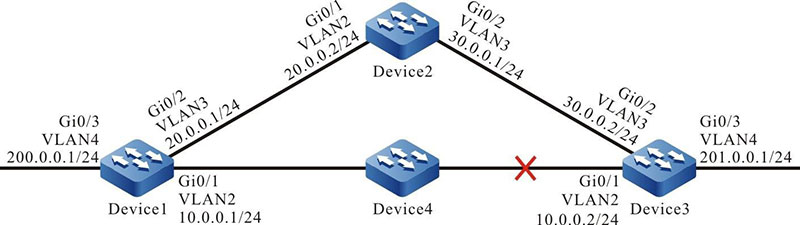
Figure 10-1 Networking of configuring the BFD basic functions
Configuration Steps
Step 1: Configure VLAN and add the port to the corresponding VLAN.(Omitted)
Step 2: Configure the interface IP address. (Omitted)
Step 3: Configure OSPF.
#Configure Device1.
|
Device1#configure terminal
Device1(config)#router ospf 100
Device1(config-ospf)#router-id 1.1.1.1
Device1(config-ospf)#network 10.0.0.0 0.0.0.255 area 0
Device1(config-ospf)#network 20.0.0.0 0.0.0.255 area 0
Device1(config-ospf)#network 200.0.0.0 0.0.0.255 area 0
Device1(config-ospf)#exit
|
#Configure Device2.
|
Device2#configure terminal
Device2(config)#router ospf 100
Device2(config-ospf)#router-id 2.2.2.2
Device2(config-ospf)#network 20.0.0.0 0.0.0.255 area 0
Device2(config-ospf)#network 30.0.0.0 0.0.0.255 area 0
Device2(config-ospf)#exit
|
#Configure Device3.
|
Device3#configure terminal
Device3(config)#router ospf 100
Device3(config-ospf)#router-id 3.3.3.3
Device3(config-ospf)#network 10.0.0.0 0.0.0.255 area 0
Device3(config-ospf)#network 30.0.0.0 0.0.0.255 area 0
Device3(config-ospf)#network 201.0.0.0 0.0.0.255 area 0
Device3(config-ospf)#exit
|
Step 4: Configure OSPF to link with BFD.
#Configure Device1.
|
Device1(config)#bfd fast-detect
Device1(config)#interface vlan2
Device1(config-if-vlan2)#ip ospf bfd
Device1(config-if-vlan2)#exit
|
#Configure Device3.
|
Device3(config)#bfd fast-detect
Device3(config)#interface vlan2
Device3(config-if-vlan2)#ip ospf bfd
Device3(config-if-vlan2)#exit
|
#View the BFD session of Device1.
Device1#show bfd session detail
Total session number: 1
OurAddr     NeighAddr    LD/RD   State Holddown   interface
10.0.0.1	10.0.0.2     12/19   UP    5000       vlan2
Type:direct
Local State:UP Remote State:UP Up for: 0h:10m:57s Number of times UP:1
Send Interval:1000ms Detection time:5000ms(1000ms*5)
Local Diag:0 Demand mode:0 Poll bit:0
MinTxInt:1000 MinRxInt:1000 Multiplier:5
Remote MinTxInt:1000 Remote MinRxInt:1000 Remote Multiplier:5
Registered protocols:OSPF
We can see that OSPF links with BFD successfully, the session is set up normally and the detection timeout is 5s.
#View the route table of Device1.
Device1#show ip route

Codes: C - Connected, L - Local, S - static, R - RIP, B - BGP, i-ISIS
       U - Per-user Static route
O - OSPF, OE-OSPF External, M - Management, E - IRMP, EX - IRMP external

C ..10.0.0.0/24 is directly connected, 00:20:01, vlan2
C   20.0.0.0/24 is directly connected, 00:25:22, vlan3
O   30.0.0.0/24 [110/2] via 20.0.0.2, 00:12:31, vlan3
                [110/2] via 10.0.0.2, 00:11:20, vlan2
C   127.0.0.0/8 is directly connected, 00:31:09, lo0
C   200.0.0.0/24 is directly connected, 00:20:10, vlan4
O   201.0.0.0/24 [110/2] via 10.0.0.2, 00:11:30, vlan2
In the route table, we can see that the route 201.0.0.0/24 first selects the line between Device1 and Device3 to communicate.
Step 5: Configure the BFD parameters.
#Configure Device1. Modify the minimum sending interval and minimum receiving interval of the BFD control packets to 100ms. The detection timeout multiples is 3.
|
Device1(config)#interface vlan2
Device1(config-if-vlan2)#bfd min-transmit-interval 100
Device1(config-if-vlan2)#bfd min-receive-interval 100
Device1(config-if-vlan2)#bfd multiplier 3
Device1(config-if-vlan2)#exit
|
#Configure Device3. Modify the minimum sending interval and minimum receiving interval of the BFD control packets to 100ms. The detection timeout multiples is 3.
|
Device3(config)#interface vlan2
Device3(config-if-vlan2)#bfd min-transmit-interval 100
Device3(config-if-vlan2)#bfd min-receive-interval 100
Device3(config-if-vlan2)#bfd multiplier 3
Device3(config-if-vlan2)#exit
|
Step 6: Check the result.
#View the BFD session of Device1.
Device1#show bfd session detail
Total session number: 1
OurAddr     NeighAddr   LD/RD    State   Holddown  interface
10.0.0.1	10.0.0.2    12/19    UP      300       vlan2
Type:direct
Local State:UP Remote State:UP Up for: 0h:11m:27s Number of times UP:1
Send Interval:100ms Detection time:300ms(100ms*3)
Local Diag:0 Demand mode:0 Poll bit:0
MinTxInt:100 MinRxInt:100 Multiplier:3
Remote MinTxInt:100 Remote MinRxInt:100 Remote Multiplier:3
Registered protocols:OSPF
After modifying the BFD parameters, the BFD detection timeout is negotiated from 5s to 300ms.
#When the line between Device1 and Device3 fails, BFD fast detects the fault and informs OSPF, and then OSPF switches the route to Device2 for communication. View the route table of Device1.
Device1#show ip route
Codes: C - Connected, L - Local, S - static, R - RIP, B BGP, i-ISIS
       U Per-user Static route
O - OSPF, OE-OSPF External, M - Management, E - IRMP, EX IRMP external

C 10.0.0.0/24 is directly connected, 00:25:00, vlan2
C 20.0.0.0/24 is directly connected, 00:30:33, vlan3
O 30.0.0.0/24 [110/2] via 20.0.0.2, 00:17:32, vlan3
C 127.0.0.0/8 is directly connected, 00:36:10, lo0
C 200.0.0.0/24 is directly connected, 00:25:11, vlan4
O 201.0.0.0/24 [110/3] via 20.0.0.2, 00:00:10, vlan3
Compared with the route table in Step 3, we can see that the route 201.0.0.0/24 is already switched to Device2 for communication.
The BFD processing mode on Device3 is similar to Device1.
 Switch


