Network Requirements
- IP Network1 and IP Network2 are two private networks of Device1 and Device3.
- IP Network1 and IP Network2 communicate with each other through the GRE tunnel between Device1 and Device3.
Network Topology
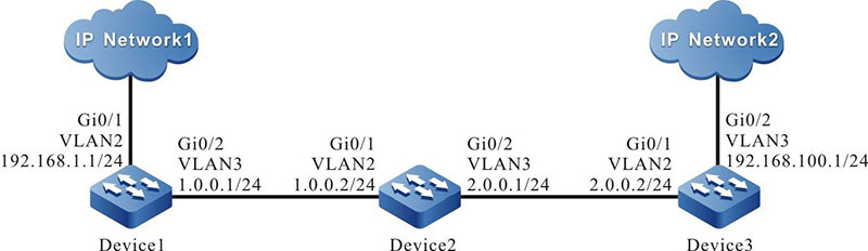
Figure 10-1 Networking for configuring GRE basic functions
Configuration Steps
Step 1: Configure VLAN, and add the port to the corresponding VLAN. (omitted)
Step 2: Configure IP addresses for all interfaces. (Omitted)
Step 3: Configure Open Shortest Path First (OSPF).
#Configure Device1.
|
Device1#configure terminal
Device1(config)#router ospf 100
Device1(config-ospf)#network 1.0.0.0 0.0.0.255 area 0
Device1(config-ospf)#exit
|
#Configure Device2.
|
Device2#configure terminal
Device2(config)#router ospf 100
Device2(config-ospf)#network 1.0.0.0 0.0.0.255 area 0
Device2(config-ospf)#network 2.0.0.0 0.0.0.255 area 0
Device2(config-ospf)#exit
|
#Configure Device3.
|
Device3#configure terminal
Device3(config)#router ospf 100
Device3(config-ospf)#network 2.0.0.0 0.0.0.255 area 0
Device3(config-ospf)#exit
|
#Query the routing table of Device3.
Device3#show ip route
Codes: C - connected, S - static, R - RIP, O - OSPF, OE-OSPF External, M - Management
 D - Redirect, E - IRMP, EX - IRMP external, o - SNSP, B - BGP, i-ISIS

Gateway of last resort is not set

O 1.0.0.0/24 [110/65536] via 2.0.0.1, 00:18:40, vlan2
C 2.0.0.0/24 is directly connected, 00:22:27, vlan2
C 192.168.100.0/24 is directly connected, 00:00:28, vlan3

-
The method for querying the routing table of Device 1 and Device2 is the same as that for Device 3, so the processes are not described here.
Step 4: Configure a GRE tunnel.
#On Device1, configure GRE tunnel tunnel1, set the source address to 1.0.0.1, destination address to 2.0.0.2, and IP address to 10.0.0.1.
|
Device1(config)#interface tunnel 1
Device1(config-if-tunnel1)#tunnel source 1.0.0.1
Device1(config-if-tunnel1)#tunnel destination 2.0.0.2
Device1(config-if-tunnel1)#ip address 10.0.0.1 255.255.255.0
Device1(config-if-tunnel1)#exit
|
#On Device3, configure GRE tunnel tunnel1, set the source address to 2.0.0.2, destination address to 1.0.0.1, and IP address to 10.0.0.2.
|
Device3(config)#interface tunnel 1
Device3(config-if-tunnel1)#tunnel source 2.0.0.2
Device3(config-if-tunnel1)#tunnel destination 1.0.0.1
Device3(config-if-tunnel1)#ip address 10.0.0.2 255.255.255.0
Device3(config-if-tunnel1)#exit
|
#Query the GRE tunnel information of Device3.
Device3#show tunnel 1
Tunnel 1:
 Tunnel mode is gre ip
 Gre checksum validation is disabled
  Gre key is not set
 Gre keepalive is disabled
 Source ipv4 address is 2.0.0.2(Source ipv4 address is up on source interface vlan2)
 Destination ipv4 address is 1.0.0.1
 Tunnel state is up
 Encapsulation vrf is global(0x0)
 TTL(time-to-live) is 255
 TOS(type of service) is not set

total(1)
-
The method for querying the GRE tunnel information of Device 1 is the same as that for Device 3, so the process is not described here.
- If a tunnel is located at different network segments, both the two devices at the two ends of the tunnel must be configured with a static route that reaches the peer tunnel with the tunnel interface as the output interface.
Step 5: Configure the static route.
#On Device1, configure the static route to the egress interface tunnel1 of IP Network2.
|
Device1(config)#ip route 192.168.100.0 255.255.255.0 tunnel1
|
#On Device3, configure the static route to the egress interface tunnel1 of IP Network1.
|
Device3(config)#ip route 192.168.1.0 255.255.255.0 tunnel1
|
#View the route table of Device3.
Device3#show ip route
Codes: C - connected, S - static, R - RIP, O - OSPF, OE-OSPF External, M - Management
       D - Redirect, E - IRMP, EX - IRMP external, o - SNSP, B - BGP, i-ISIS

Gateway of last resort is not set

O 1.0.0.0/24 [110/65536] via 2.0.0.1, 00:43:30, vlan2
C 2.0.0.0/24 is directly connected, 00:47:17, vlan2
C 10.0.0.0/24 is directly connected, 00:17:12, tunnel1
S 192.168.1.0/24 [1/100000] is directly connected, 00:00:10, tunnel1
-
The method for querying the routing table of Device 1 is the same as that for Device 3, so the process is not described here.
 Switch


