Network Requirements
- PC1 and PC2 are connected with Device1 and communicate with each other in VLAN2; PC3 is connected with Device2.
- Configure RSPAN on Device1 and Device2; PC3 monitors the packets received and sent by port gigabitethernet0/1 of Device1 via RSPAN VLAN3.
Network Topology
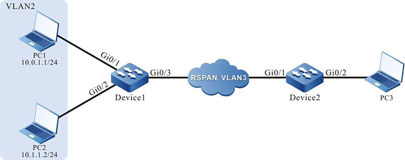
Figure 5-2 Networking of configuring the RSPAN
Configuration Steps
Step 1: Configure the link type of the VLAN and port.
#Create VLAN2 on Device1. Device1#configure terminal Device1(config)#vlan 2
|
Device1#configure terminal
Device1(config)#vlan 2
Device1(config-vlan2)#exit
|
#Configure the link type of port gigabitethernet0/1 and gigabitethernet0/2 on Device1 as Access, permitting the services of VLAN2 to pass.
|
Device1(config)#interface gigabitethernet 0/1-0/2
Device1(config-if-range)#switchport mode access
Device1(config-if-range)#switchport access vlan 2
Device1(config-if-range)#exit
|
#Configure the link type of port gigabitethernet0/3 as Trunk on Device1.
|
Device1(config)#interface gigabitethernet 0/3
Device1(config-if-gigabitethernet0/3)#switchport mode trunk
Device1(config-if-gigabitethernet0/3)#exit
|
#Configure the link type of port gigabitethernet0/1 as Trunk on Device2.
|
Device2(config)#interface gigabitethernet 0/1
Device2(config-if-gigabitethernet0/1)#switchport mode trunk
Device2(config-if-gigabitethernet0/1)#exit
|
#Configure the link type of port gigabitethernet0/2 as Hybrid on Device2.
|
Device2(config)#interface gigabitethernet 0/2
Device2(config-if-gigabitethernet0/2)#switchport mode hybrid
Device2(config-if-gigabitethernet0/2)#exit
|
Step 2: Configure RSPAN on Device1 and Device2.
#Configure VLAN3 as RSPAN VLAN on Device1 and configure port gigabitethernet0/3 to permit the services of VLAN3 to pass.
|
Device1(config)#vlan 3
Device1(config-vlan3)#remote-span
Device1(config-vlan3)#exit
Device1(config)#interface gigabitethernet 0/3
Device1(config-if-gigabitethernet0/3)#switchport trunk allowed vlan add 3
Device1(config-if-gigabitethernet0/3)#exit
|
#Configure RSPAN on Device1, the mirror source session is port gigabitethernet0/1, and destination session is port gigabitethernet0/3.
|
Device1(config)#monitor session 1 source interface gigabitethernet 0/1 both
Device1(config)#monitor session 1 destination remote vlan 3 interface gigabitethernet 0/3
|
#View the RSPAN session information on Device1.
Device1#show monitor session all
Session 1
Type             : RSPAN Source Session
RSPAN VLAN       : 3
Destination Interface : gigabitethernet0/3
Source Interface(both): gi0/1
#Configure VLAN3 as RSPAN VLAN on Device2 and configure port gigabitethernet0/1 to permit the services of VLAN3 to pass.
|
Device2(config)#vlan 3
Device2(config-vlan3)#remote-span
Device2(config-vlan3)#exit
Device2(config)#interface gigabitethernet 0/1
Device2(config-if-gigabitethernet0/1)# switchport trunk allowed vlan add 3
Device2(config-if-gigabitethernet0/1)#exit
|
#Configure RSPAN on Device2, the mirror source session is RSPAN VLAN3, and destination session is port gigabitethernet0/2.
|
Device2(config)#monitor session 1 source remote vlan 3
Device2(config)#monitor session 1 destination interface gigabitethernet 0/2
|
#View the RSPAN session information on Device2.
Device2#show monitor session all
Session 1
Type             : RSPAN
Destination Session RSPAN VLAN      : 3
Destination Interface : gigabitethernet0/2
Step 3: Check the result.
#When PC1 and PC2 communicate with each other, the packets sent and received by port gigabitethernet0/1 of Device1 can be got on PC3.
 Switch


