Network Requirements
- All devices are in one L2 network.
- The data traffic of data1 is transmitted via device2-device1, and the data traffic of Data2 is transmitted via device4-device3, realizing the load balance and providing the link backup.
Network Topology
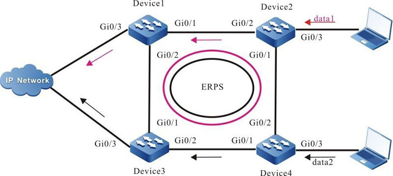
Figure 11-2 Configure ERPS load
Configuration Steps
Step 1: Configure vlan and port link type.
#On Device1–Device4, create VLAN2-VLAN3, VLAN100-VLAN200, and VLAN300-VLAN400, and configure the link type of ports gigabitethernet0/1 and gigabitethernet0/2 as Trunk, permitting the services of VLAN2-VLAN3, VLAN100-VLAN200, and VLAN300-VLAN400 to pass.
|
Device1#configure terminal
Device1(config)#vlan 2,100-200
Device1(config)# interface gigabitethernet 0/1
Device1(config-if-gigabitethernet0/1)#shutdown
Device1(config-if-gigabitethernet0/1)# switchport mode trunk
Device1(config-if-gigabitethernet0/1)# no switchport trunk allowed vlan all
Device1(config-if-gigabitethernet0/1)# switchport trunk allowed vlan add 2,100-200
Device1(config-if-gigabitethernet0/1)# switchport trunk allowed vlan add 3,300-400
Device1(config-if-gigabitethernet0/1)#exit
Device1(config)# interface gigabitethernet 0/2
Device1(config-if-gigabitethernet0/1)# switchport mode trunk
Device1(config-if-gigabitethernet0/1)# no switchport trunk allowed vlan all
Device1(config-if-gigabitethernet0/1)# switchport trunk allowed vlan add 2,100-200
Device1(config-if-gigabitethernet0/1)# switchport trunk allowed vlan add 3,300-400
Device1(config-if-gigabitethernet0/1)#end
|
Step 2: Configure the MST instance.
# On Device1–Device4, configure MST instance 1 to map vlan100-200, configure MST instance 2 to map vlan300-400, and activate the instance.
|
Device1#configure terminal
Device1(config)# spanning-tree mst configuration
Device1(config-mst)# instance 1 vlan 100-200
Device1(config-mst)# instance 2 vlan 300-400
Device1(config-mst)# active configuration pending
Device1(config-mst)#end
|
Step 3: Configure ERPS.
#On Device1, configure ERPS ring1, configures vlan2 as control VLAN of ring1, configure gigabitethernet0/1 as the normal port of ring1, configure gigabitethernet0/2 as the normal port of ring1, configure instance 1 as data VLAN of ring1, and enable ERPS function of ring1.
|
Device1# configure terminal
Device1(config)#erps ring 1
Device1(config-erps1)# control vlan 2
Device1(config-erps1)# port0 interface g0/1
Device1(config-erps1)# port1 interface g0/2
Device1(config-erps1)# instance 1
Device1(config-erps1)# erps enable
Device1(config-erps1)# end
|
#On Device1, configure ERPS ring2, configures vlan3 as control VLAN of ring2, configure gigabitethernet0/1 as the normal port of ring2, configure gigabitethernet0/2 as the normal port of ring2, configure instance 2 as data VLAN of ring2, and enable the ERPS function of ring2.
|
Device1# configure terminal
Device1(config)#erps ring 2
Device1(config-erps1)# control vlan 3
Device1(config-erps1)# port0 interface g0/1
Device1(config-erps1)# port1 interface g0/2
Device1(config-erps1)# instance 2
Device1(config-erps1)# erps enable
Device1(config-erps1)# exit
Device1(config)# interface gigabitethernet 0/1
Device1(config-if-gigabitethernet0/1)#no shutdown
Device1(config-if-gigabitethernet0/1)# end
|
#On Device2, configure ERPS ring1, configures vlan2 as control VLAN of ring1, configure gigabitethernet0/1 as the owner port of ring1, configure gigabitethernet0/2 as the normal port of ring1, configure instance 1 as data VLAN of ring1, and enable ERPS function of ring1.
|
Device2# configure terminal
Device2(config)#erps ring 1
Device2(config-erps1)# control vlan 2
Device2(config-erps1)# port0 interface g0/1 rpl owner
Device2(config-erps1)# port1 interface g0/2
Device2(config-erps1)# instance 1
Device2(config-erps1)# erps enable
Device2(config-erps1)# exit
|
#On Device2, configure ERPS ring2, configures vlan3 as control VLAN of ring2, configure gigabitethernet0/1 as the neighbor port of ring2, configure gigabitethernet0/2 as the normal port of ring2, configure instance 2 as data VLAN of ring2, and enable the ERPS function of ring2.
|
Device2# configure terminal
Device2(config)#erps ring 1
Device2(config-erps1)# control vlan 3
Device2(config-erps1)# port0 interface g0/1 rpl neighbor
Device2(config-erps1)# port1 interface g0/2
Device2(config-erps1)# instance 2
Device2(config-erps1)# erps enable
Device2(config-erps1)# exit
Device2(config)# interface gigabitethernet 0/1
Device2(config-if-gigabitethernet0/1)#no shutdown
Device2(config-if-gigabitethernet0/1)# end
|
#On Device3, configure ERPS ring1, configures vlan2 as control VLAN of ring1, configure gigabitethernet0/1 as the normal port of ring1, configure gigabitethernet0/2 as the normal port of ring1, configure instance 1 as data VLAN of ring1, and enable ERPS function of ring1.
|
Device3# configure terminal
Device3(config)#erps ring 1
Device3(config-erps1)# control vlan 2
Device3(config-erps1)# port0 interface g0/1 rpl neighbor
Device3(config-erps1)# port1 interface g0/2
Device3(config-erps1)# instance 1
Device3(config-erps1)# erps enable
Device3(config-erps1)# exit
|
#On Device3, configure ERPS ring2, configures vlan3 as control VLAN of ring2, configure gigabitethernet0/1 as the neighbor port of ring2, configure gigabitethernet0/2 as the normal port of ring2, configure instance 2 as data VLAN of ring2, and enable the ERPS function of ring2.
|
Device3# configure terminal
Device3(config)#erps ring 2
Device3(config-erps1)# control vlan 3
Device3(config-erps1)# port0 interface g0/1
Device3(config-erps1)# port1 interface g0/2
Device3(config-erps1)# instance 2
Device3(config-erps1)# erps enable
Device3(config-erps1)# exit
Device3(config)# interface gigabitethernet 0/1
Device3(config-if-gigabitethernet0/1)#no shutdown
Device3(config-if-gigabitethernet0/1)# end
|
#On Device4, configure ERPS ring1, configures vlan2 as control VLAN of ring1, configure gigabitethernet0/1 as the normal port of ring1, configure gigabitethernet0/2 as the neighbor port of ring1, configure instance 1 as data VLAN of ring1, and enable ERPS function of ring1.
|
Device4# configure terminal
Device4(config)#erps ring 1
Device4(config-erps1)# control vlan 2
Device4(config-erps1)# port0 interface g0/1
Device4(config-erps1)# port1 interface g0/2 rpl neighbour
Device4(config-erps1)# instance 1
Device4(config-erps1)# erps enable
Device4(config-erps1)# exit
|
#On Device4, configure ERPS ring2, configures vlan3 as control VLAN of ring2, configure gigabitethernet0/1 as the normal port of ring2, configure gigabitethernet0/2 as the owner port of ring2, configure instance 2 as data VLAN of ring2, and enable the ERPS function of ring2.
|
Device4# configure terminal
Device4(config)#erps ring 2
Device4(config-erps1)# control vlan 3
Device4(config-erps1)# port0 interface g0/1
Device4(config-erps1)# port1 interface g0/2 rpl owner
Device4(config-erps1)# instance 2
Device4(config-erps1)# erps enable
Device4(config-erps1)# exit
Device4(config)# interface gigabitethernet 0/1
Device4(config-if-gigabitethernet0/1)#no shutdown
Device4(config-if-gigabitethernet0/1)# end
|
Step 4: Check the result.
#After the netwotk topology becomes stable, query the ERPS information of the Device, and take device2 as an example.
#Query the ERPS information of Device2.
Device2# show erps ring 1 detail
Ring ID       : 1
Version       : v2
R-APS mel     : 7
Instance      : 1 vlans mapped : 100-200
Control VLAN  : 2
Node role     : Owner
Node state    : idle
Guard timer   : 500 ms       Running : 0 ms
Holdoff timer : 0 ms         Running : 0 ms
WTR timer     : 5 min        Running : 0 s
WTB timer     : 7 s          Running : 0 s
Subring       : No
Tc-limit enable : No
Tc-limit Interval : 2 Tc-limit
Threshold : 3
Revertive operation : Revertive
R-APS channel : Non-Virtual channel
Enable status : Enable
Gigabitethernet0/1 Flush Logic
    Remote Node ID : 0000-0000-0000
    Remote BPR     : 0
Gigabitethernet0/1 track CFM
    MD Name   :
    MA Name   :
    MEP ID    : 0
    RMEP ID   : 0
    CFM State : 0
Gigabitethernet0/2 Flush Logic
    Remote Node ID : 0000-0000-0000
    Remote BPR     : 0
Gigabitethernet0/2 track CFM
    MD Name   :
    MA Name   :
    MEP ID    : 0
    RMEP ID   : 0
    CFM State : 0
Port   Name                    PortRole  SwitchType  PortStatus   SignalStatus
------------------------------------------------------------------------------
Port0  gigabitethernet0/1      Owner-----------------Blocking     Non-failed
Port1 gigabitethernet0/2       Normal----------------Forwarding   Non-failed

Device2# show erps ring 2 detail
Ring ID       : 2
Version       : v2
R-APS mel     : 7
Instance      : 1 vlans mapped	100-200
Control VLAN  : 3
Node role     : Neighbour
Node state    : idle
Guard timer   : 500 ms       Running : 0 ms
Holdoff timer : 0 ms         Running : 0 ms
WTR timer     : 5 min        Running : 0 s
WTB timer     : 7 s          Running : 0 s
Subring       : No
Tc-limit enable : No Tc-limit
Interval : 2 Tc-limit
Threshold : 3
Revertive operation : Revertive
R-APS channel : Non-Virtual channel
Enable status : Enable
Gigabitethernet0/1 Flush Logic
    Remote Node ID : 0000-0000-0000
    Remote BPR     : 0
Gigabitethernet0/1 track CFM
    MD Name   :
    MA Name   :
    MEP ID    : 0
    RMEP ID   : 0
    CFM State : 0
Gigabitethernet0/2 Flush Logic
    Remote Node ID : 0000-0000-0000
    Remote BPR     : 0
Gigabitethernet0/2 track CFM
    MD Name   :
    MA Name   :
    MEP ID    : 0
    RMEP ID   : 0
    CFM State : 0
Port   Name                  PortRole  SwitchType  PortStatus  SignalStatus
---------------------------------------------------------------------
Port0  gigabitethernet0/1    Neighbour-------------Blocking    Non-failed
Port1  gigabitethernet0/2    Normal----------------Forwarding  Non-failed

-
When loading, multiple logical rings on one physical ring cannot be configured with the same data instance.
 Switch


