Network Requirements
- Configure OSPF for all devices, and divide the devices into three areas: Area 0, Area 1, and Area 2. After configuration, all devices should be able to learn routes from each other.
- On a back-to-back Ethernet interface, to speed up set of OSPF neighbors, you can change the network type of the OSPF interface to P2P. Modify the network type of the interfaces in Area 2 to P2P. After the configuration, all devices can learn routes from each other.
Network Topology
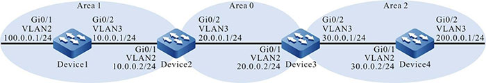
Figure 7-1 Networking for Configuring Basic OSPF Functions
Configuration Steps
Step 1: Create VLANs, and add ports to the required VLANs. (Omitted)
Step 2: Configure IP addresses for the ports. (Omitted)
Step 3: Configure an OSPF process and let the interface cover different areas.
#On Device1, configure an OSPF process and configure the interfaces to cover area 1.
|
Device1#configure terminal
Device1(config)#router ospf 100
Device1(config-ospf)#router-id 1.1.1.1
Device1(config-ospf)#network 10.0.0.0 0.0.0.255 area 1
Device1(config-ospf)#network 100.0.0.0 0.0.0.255 area 1
Device1(config-ospf)#exit
|
#On Device2, configure an OSPF process and configure the interfaces to cover Area 0 and Area 1.
|
Device2#configure terminal
Device2(config)#router ospf 100
Device2(config-ospf)#router-id 2.2.2.2
Device2(config-ospf)#network 20.0.0.0 0.0.0.255 area 0
Device2(config-ospf)#network 10.0.0.0 0.0.0.255 area 1
Device2(config-ospf)#exit
|
#On Device3, configure an OSPF process and configure the interfaces to cover Area 0 and Area 2.
|
Device3#configure terminal
Device3(config)#router ospf 100
Device3(config-ospf)#router-id 3.3.3.3
Device3(config-ospf)#network 20.0.0.0 0.0.0.255 area 0
Device3(config-ospf)#network 30.0.0.0 0.0.0.255 area 2
Device3(config-ospf)#exit
|
#On Device4, configure an OSPF process and configure the interfaces to cover area 2.
|
Device4#configure terminal
Device4(config)#router ospf 100
Device4(config-ospf)#router-id 4.4.4.4
Device4(config-ospf)#network 30.0.0.0 0.0.0.255 area 2
Device4(config-ospf)#network 200.0.0.0 0.0.0.255 area 2
Device4(config-ospf)#exit
|

-
A Router IDs can be manually configured or automatically generated. If a Router ID is not manually configured, the device automatically selects a Router ID. The device first selects the largest IP address among Loopback interface IP addresses as the Router ID. If the device is not configured with Loopback interface IP addresses, then it selects the largest IP addresses among common interface IP addresses as the Router ID. Only when an interface is in the UP status can the IP address of the interface be selected as the Router ID.
- In using the network command, the wildcard mask need not accurately match the mask length of the interface IP addresses, but the network segment needs to cover the interface IP addresses. For example, network 0.0.0.0 255.255.255.255 means to cover all interfaces.
#Query the OSPF neighbors and routing table of Device1.
Device1#show ip ospf neighbor OSPF process 100:
Neighbor ID  Pri   State     Dead Time   Address    Interface
2.2.2.2      1     Full/DR   00:00:36	 10.0.0.2   vlan3

Device1#show ip route
Codes: C - connected, S - static, R - RIP, O - OSPF, OE-OSPF External, M Management
       D - Redirect, E - IRMP, EX - IRMP external, o - SNSP, B - BGP, i-ISIS

Gateway of last resort is not set

C 10.0.0.0/24 is directly connected, 02:26:21, vlan3
O 20.0.0.0/24 [110/2] via 10.0.0.2, 02:25:36, vlan3
O 30.0.0.0/24 [110/3] via 10.0.0.2, 02:25:36, vlan3
C 100.0.0.0/24 is directly connected, 02:26:23, vlan2
C 127.0.0.0/8 is directly connected, 18:09:44, lo0
O 200.0.0.0/24 [110/4] via 10.0.0.2, 02:25:36, vlan3
#Query the OSPF neighbors and routing table of Device2.
Device2#show ip ospf neighbor OSPF process 100:
Neighbor ID   Pri   State         Dead Time   Address     Interface
1.1.1.1       1     Full/Backup   00:00:37    10.0.0.1    vlan2
3.3.3.3       1     Full/DR       00:00:38    20.0.0.2    vlan3

Device2#show ip route
Codes: C - connected, S - static, R - RIP, O - OSPF, OE-OSPF External, M Management
       D - Redirect, E - IRMP, EX - IRMP external, o - SNSP, B BGP, i-ISIS

Gateway of last resort is not set

C 10.0.0.0/24 is directly connected, 02:31:15, vlan2
C 20.0.0.0/24 is directly connected, 02:31:50, vlan3
O 30.0.0.0/24 [110/2] via 20.0.0.2, 02:31:40, vlan3
O 100.0.0.0/24 [110/2] via 10.0.0.1, 02:30:29, vlan2
C 127.0.0.0/8 is directly connected, 240:21:34, lo0
O 200.0.0.0/24 [110/3] via 20.0.0.2, 02:31:40, vlan3
#Query OSPF Link Status Database (LSDB) of Device2.
Device2#show ip ospf database
            OSPF Router with ID (2.2.2.2) (Process ID 100)
                Router Link States (Area 0)

Link ID    ADV Router   Age  Seq#        CkSum Link count
2.2.2.2    2.2.2.2      1777 0x8000000c  0xcb20 1
3.3.3.3    3.3.3.3      309  0x8000000a  0x9153 1

                Net Link States (Area 0)

Link ID    ADV Router   Age  Seq#        CkSum
20.0.0.2   3.3.3.3      369  0x80000006  0xec12

                Summary Link States (Area 0)

Link ID     ADV Router  Age  Seq#        CkSum    Route
10.0.0.0    2.2.2.2     1757 0x80000005  0xcc59   10.0.0.0/24
100.0.0.0   2.2.2.2     1356 0x80000005  0x408a   100.0.0.0/24
30.0.0.0    3.3.3.3     9    0x80000006  0xa765   30.0.0.0/24
200.0.0.0   3.3.3.3     149  0x80000006  0x075a   200.0.0.0/24

                Router Link States (Area 1)

Link ID      ADV Router  Age  Seq#        CkSum Link count
1.1.1.1      1.1.1.1     1775 0x80000009  0xbbda 2
2.2.2.2      2.2.2.2     1737 0x80000008  0x2dd5 1

                Net Link States (Area 1)

Link ID      ADV Router  Age  Seq#        CkSum
10.0.0.2     2.2.2.2     34   0x80000006  0x39db

                Summary Link States (Area 1)

Link ID      ADV Router  Age  Seq#        CkSum Route

20.0.0.0	 2.2.2.2     144  0x80000006  0x48d2 20.0.0.0/24
30.0.0.0     2.2.2.2     1186 0x80000005  0xd13f 30.0.0.0/24
200.0.0.0    2.2.2.2     14   0x80000006  0x2f35 200.0.0.0/24
For Device2, routes 30.0.0.0/24 and 200.0.0.0/24 are inter-area routes. You can query the LSA information of the related routes in Summary Link States (Area 0). In the case of intra-area routes, run the show ip ospf database router command to query the LSA information of the related routes.
Step 4: Configure the network type of OSPF interfaces to P2P.
#On Device3, configure the OSPF network type of interface VLAN3 to P2P.
|
Device3(config)#interface vlan3
Device3(config-if-vlan3)#ip ospf network point-to-point
Device3(config-if-vlan3)#exit
|
#On Device4, configure the OSPF network type of interface VLAN2 to P2P.
|
Device4(config)#interface vlan2
Device4(config-if-vlan2)#ip ospf network point-to-point
Device4(config-if-vlan2)#exit
|
Step 5: Check the result.
#Query the OSPF neighbors and routing table of Device3.
Device3#show ip ospf neighbor OSPF process 100:
Neighbor ID   Pri  State        Dead Time   Address    Interface
2.2.2.2       1    Full/Backup  00:00:36	20.0.0.1   vlan2
4.4.4.4       1    Full/ -      00:00:39    30.0.0.2   vlan3

Device3#show ip route
Codes: C - connected, S - static, R - RIP, O - OSPF, OE-OSPF External, M Management
       D - Redirect, E - IRMP, EX - IRMP external, o - SNSP, B BGP, i-ISIS

Gateway of last resort is not set

O 10.0.0.0/24 [110/2] via 20.0.0.1, 00:02:53, vlan2
C 20.0.0.0/24 is directly connected, 03:20:36, vlan2
C 30.0.0.0/24 is directly connected, 03:20:26, vlan3
O 100.0.0.0/24 [110/3] via 20.0.0.1, 00:01:51, vlan2
C 127.0.0.0/8 is directly connected, 262:01:24, lo0
O 200.0.0.0/24 [110/2] via 30.0.0.2, 00:00:11, vlan3
-
If OSPF neighbor relations are set up in a P2P network, no DR or BDR election will be performed.
#Query the OSPF neighbors and routing table of Device4.
Device4#show ip ospf neighbor

OSPF process 100:
Neighbor ID   Pri  State      Dead Time   Address    Interface
3.3.3.3       1    Full/ -    00:00:39	  30.0.0.1   vlan2

Device4#show ip route
Codes: C - connected, S - static, R - RIP, O - OSPF, OE-OSPF External, M Management
       D - Redirect, E - IRMP, EX - IRMP external, o - SNSP, B BGP, i-ISIS

Gateway of last resort is not set

O 10.0.0.0/24 [110/3] via 30.0.0.1, 00:01:04, vlan2
O 20.0.0.0/24 [110/2] via 30.0.0.1, 00:01:04, vlan2
C 30.0.0.0/24 is directly connected, 03:20:25, vlan2
O 100.0.0.0/24 [110/4] via 30.0.0.1, 00:01:04, vlan2
C 127.0.0.0/8 is directly connected, 22:52:36, lo0
C 200.0.0.0/24 is directly connected, 03:20:13, vlan3
After the network type of OSPF interfaces are modified to P2P, neighbors can be set up normally, and routes can be learned normally.
-
In configuring network types for OSPF interfaces, the network types of OSPF interfaces at the two ends of neighbors must be the same; otherwise, routing learning and flooding will be affected. By default, the network type of an OSPF interface is determined by the network type of the physical interface.
 Switch


