Network Requirements
- RIPv2 runs between Device1, Device2, and Device3 for route interaction.
- Device1 learns route 3.0.0.0/24 from Device2 and Device3. Then, configure route metric offset so that Device1 selects the route advertised by Device2 with priority. At this time, the line between Device1 and Device2 becomes the main line of the route. The line between Device1 and Device3 becomes and backup line of the route.
- On Device1, configure an RIP backup interface. If the main line is normal, the route passes the main line. If the main line is faulty, the route quickly switches to the backup line.
Network Topology
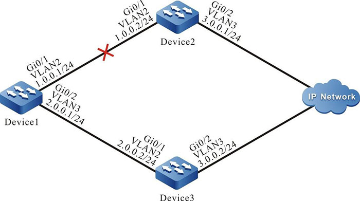
Figure 5-7 Networking for Configuring an RIP Backup Interface
Configuration Steps
Step 1: Create VLANs, and add ports to the required VLANs. (Omitted)
Step 2: Configure IP addresses for the ports. (Omitted)
Step 3: Configure RIP.
#Configure Device1.
|
Device1#configure terminal
Device1(config)#router rip
Device1(config-rip)#version 2
Device1(config-rip)#network 1.0.0.0
Device1(config-rip)#network 2.0.0.0
Device1(config-rip)#exit
|
#Configure Device2.
|
Device2#configure terminal
Device2(config)#router rip
Device2(config-rip)#version 2
Device2(config-rip)#network 1.0.0.0
Device2(config-rip)#network 3.0.0.0
Device2(config-rip)#exit
|
#Configure Device3.
|
Device3#configure terminal
Device3(config)#router rip
Device3(config-rip)#version 2
Device3(config-rip)#network 2.0.0.0
Device3(config-rip)#network 3.0.0.0
Device3(config-rip)#exit
|
#Query the routing table of Device1.
Device1#show ip route
Codes: C - Connected, L - Local, S - static, R - RIP, B - BGP, i-ISIS
       U - Per-user Static route
       O - OSPF, OE-OSPF External, M - Management, E - IRMP, EX - IRMP external

C 1.0.0.0/24 is directly connected, 01:30:23, vlan2
C 2.0.0.0/24 is directly connected, 01:30:14, vlan3
R 3.0.0.0/24 [120/1] via 1.0.0.2, 01:20:44, vlan2
             [120/1] via 2.0.0.2, 00:00:02, vlan3
C 127.0.0.0/8 is directly connected, 77:58:18, lo0
Device1 has learnt route 3.0.0.0/24 from both Device2 and Device3.
Step 4: Configure a route metric offset.
#On Device1, configure a route metric offset in the input direction of interface VLAN3 so that the metric of the routes that match ACL is increased to 3.
|
Device1(config)#ip access-list standard 1
Device1(config-std-nacl)#permit 3.0.0.0 0.0.0.255
Device1(config-std-nacl)#commit
Device1(config)#exit
Device1(config)#router rip
Device1(config-rip)#offset-list 1 in 3 vlan3
Device1(config-rip)#exit
|
#Query the routing table of Device1.
Device1#show ip route
Codes: C - Connected, L - Local, S - static, R - RIP, B BGP, i-ISIS
       U Per-user Static route
       O - OSPF, OE-OSPF External, M - Management, E - IRMP, EX IRMP external

C 1.0.0.0/24 is directly connected, 01:30:23, vlan2
C 2.0.0.0/24 is directly connected, 01:30:14, vlan3
R 3.0.0.0/24 [120/1] via 1.0.0.2, 01:20:44, vlan2
C 127.0.0.0/8 is directly connected, 77:58:18, lo0
After the route metric offset is configured, Device1 selects route 3.0.0.0/24 advertised by Device2.
Step 5: Configure a backup interface.
#On Device1, configure interface VLAN3 as the RIP backup interface of VLAN2.
|
Device1(config)#interface vlan2
Device1(config-if-vlan2)#ip rip standby vlan3
Device1(config-if-vlan2)#exit
|
Step 6: Check the result.
#If the line between Device1 and Device2 becomes faulty, the route can quickly switch over to the backup line between Device1 and Device3.
#On Device1, query the route information.
Device1#show ip route
Codes: C - Connected, L - Local, S - static, R - RIP, B - BGP, i-ISIS
       U - Per-user Static route
       O - OSPF, OE-OSPF External, M - Management, E - IRMP, EX - IRMP external

C 2.0.0.0/24 is directly connected, 02:07:47, vlan3
R 3.0.0.0/24 [120/4] via 2.0.0.2, 00:01:14, vlan3
C 127.0.0.0/8 is directly connected, 78:35:51, lo0
 Switch


