Network Requirement
- Device1 and Device2 form the stacking system and serve as the MVST master device; Device3, Device4, and Device5 serve as the extended card and the last ports of the extended card are connected to the MVST master device.
- The master device configures the auto detection upgrade. When Device3, Device4, and Device5 are added to the MVST domain as the extended card, the extended card can upgrade automatically.
Network Topology
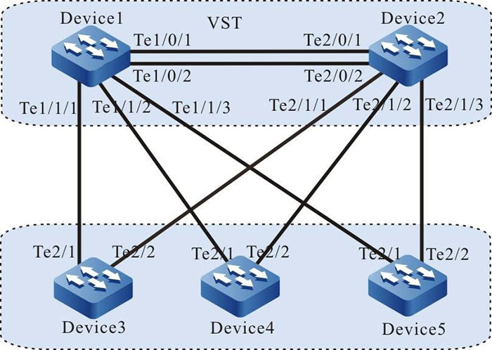
Figure 3-2 Configure the auto detection upgrade
Configuration Steps
Step 1: Configure the VST system.
#On Device1, configure the virtual switch member device No. to 1, and the domain No. to 10, and the priority to 255.
|
Device1#configure terminal
Device1(config)#switch virtual member 1
Do you want to modify member id(Yes|No)?y
% Member ID 1 config will take effect only after the exec command 'switch mode virtual' is issued
Device1(config-vst-member-1)#domain 10
% Domain ID 10 config will take effect only after the exec command 'switch mode virtual' is issued
Device1(config-vst-member-1)#priority 255
Device1(config-vst-member-1)#exit
|
#On Device1, create virtual switch link interface 1, and add ports tentengigabitethernet0/1 and tentengigabitethernet0/2 to virtual switch link interface 1.
|
Device1(config)#vsl-channel 1
Device1(config-vsl-channel-1)#exit
Device1(config)#interface tentengigabitethernet 0/1
Device1(config-if-tentengigabitethernet0/1)#vsl-channel 1 mode on
Device1(config-if-tentengigabitethernet0/1)#exit
Device1(config)#interface tentengigabitethernet 0/2
Device1(config-if-tentengigabitethernet0/2)#vsl-channel 1 mode on
Device1(config-if-tentengigabitethernet0/2)#exit
|
#On Device 1, save the configuration.
|
Device1#write
Are you sure to overwrite /flash/startup (Yes|No)?y
Building Configuration...done
Write to startup file.. OK
Write to mode file.. OK
|
#On Device2, configure the virtual switch member device No. to 2, and the domain No. to 10, and the priority to 200.
|
Device2#configure terminal
Device2(config)#switch virtual member 2
Do you want to modify member id(Yes|No)?y
% Member ID 2 config will take effect only after the exec command 'switch mode virtual' is issued
Device2(config-vst-member-2)#domain 10
% Domain ID 10 config will take effect only after the exec command 'switch mode virtual' is issued
Device2(config-vst-member-2)#priority 200
Device2(config-vst-member-2)#exit
|
#On Device2, create virtual switch link interface 1, and add port tentengigabitethernet1/1to virtual switch link interface 1.
|
Device2(config)#vsl-channel 1
Device2(config-vsl-channel-1)#exit
Device2(config)#interface tentengigabitethernet 0/1
Device2(config-if-tentengigabitethernet0/1)#vsl-channel 1 mode on
Device2(config-if-tentengigabitethernet0/1)#exit
Device2(config)#interface tentengigabitethernet 0/2
Device2(config-if-tentengigabitethernet0/2)#vsl-channel 1 mode on
Device2(config-if-tentengigabitethernet0/2)#exit
|
#On Device2, save the configuration.
|
Device2#write
Are you sure to overwrite /flash/startup (Yes|No)?y
Building Configuration.. done
Write to startup file.. OK
Write to mode file.. OK
|
#Configure Device1 running mode to the stacking mode.
|
Device1#switch mode virtual
This command will convert all interface names to naming convention "interface-type member-number/slot/interface",
Please make sure to save current configuration.Do you want to proceed? (yes|no)?y
Converting interface names Building configuration..
Copying the startup configuration to backup file named "startup-backupalone"..
Please wait system reloading is in progress!
ok
Reset system!
%SYS-5-RELOAD: Reload requested
|
#Configure the running mode of Device2 to the stacking mode.
|
Device2#switch mode virtual
This command will convert all interface names to naming convention "interface-type member-number/slot/interface",
Please make sure to save current configuration.Do you want to proceed? (yes|no)?y
Converting interface names Building configuration...
Copying the startup configuration to backup file named "startup-backupalone"...
Please wait...system reloading is in progress!
ok
Reset system!
%SYS-5-RELOAD: Reload requested
|
#After restarting, view on Device1, the stacking system is formed, and Device1 is the master device of the stacking system.
Device1#show switch virtual
Codes: L - local-device,I - isolate-device

Virtual Switch Mode        : VIRTUAL
Virtual Switch DomainId    : 10
Virtual Switch mac-address : 0001.7a6a.0255

---------------VST MEMBER INFORMATION--------------------------
CODE MemberID Role    Pri  LocalVsl          RemoteVsl
---------------------------------------------------------------
L    1        Master  255  vsl-channel 1/1   vsl-channel 2/1
     2        Member  200  vsl-channel 2/1   vsl-channel 1/1
Sep 2: Configure the MVST basic functions.
#On Device1, configure the stacking system as the MVST management device.
|
Device1(config)#mvst enable
%MVST-NOTIFY-5: MVST is enabled !
Device1(config)#mvst master
Device1(config)#mvst domain-name test
|
#On Device1, configure the link aggregation of the stacking system, and enable the MVST detection.
|
Device1(config)#mvst link-aggregation 1 mode lacp
Device1(config)# mvst interface tengigabitethernet 1/1/1,2/1/1 join link-aggregation 1 active
Device1(config)#interface link-aggregation 1
Device1(config-link-aggregation1)#mvst inspection
Device1(config-link-aggregation1)#exit
Device1(config)#mvst link-aggregation 2 mode lacp
Device1(config)# mvst interface tengigabitethernet 1/1/2,2/1/2 join link-aggregation 2 active
Device1(config)#interface link-aggregation 2
Device1(config-link-aggregation2)#mvst inspection
Device1(config-link-aggregation2)#exit
Device1(config)#mvst link-aggregation 3 mode lacp
Device1(config)# mvst interface tengigabitethernet 1/1/3,2/1/3 join link-aggregation 3 active
Device1(config)#interface link-aggregation 3
Device1(config-link-aggregation3)#mvst inspection
Device1(config-link-aggregation3)#exit
|
#On Device3, enable the MVST function.
|
Device3#configure terminal
Device3(config)#mvst enable
%MVST-NOTIFY-5: interface tengigabitethernet2/1 and interface tengigabitethernet2/2 join link-aggregation 1 successfully.
%MVST-NOTIFY-5: MVST is enabled !
|
#On Device4, enable the MVST function.
|
Device4#configure terminal
Device4(config)#mvst enable
%MVST-NOTIFY-5: interface tengigabitethernet2/1 and interface tengigabitethernet2/2 join link-aggregation 1 successfully.
%MVST-NOTIFY-5: MVST is enabled !
|
#On Device5, enable the MVST function.
|
Device5#configure terminal
Device5(config)#mvst enable
%MVST-NOTIFY-5: interface tengigabitethernet2/1 and interface tengigabitethernet2/2 join link-aggregation 1 successfully.
%MVST-NOTIFY-5: MVST is enabled !
|
Step 3: Configure auto upgrade detection.
#On Device1, configure auto upgrade detection, specify the upgrade version of the extended card, and add the clear, reload, and write parameters.
|
Device1(config)# mvst auto update image /usb/sp35-g-9.5.0.2(R).pck clear reload write
|
#On Device1, check the configuration result.
Device1#show mvst auto-update config
------------------------------------------------------------------
 	 FLAG Codes:
   C -- Clear bin/pck space when slave slot space is not enough
   R -- Reload slave slot when update slave slot successfully
   W -- Save slave slot current configuration to startup-config
------------------------------------------------------------------
ID IMAGE-NAME                 IMAGE-PATH                  OPTION
------------------------------------------------------------------
1  sp35-g-9.5.0.2(R).pck      /usb/sp35-g-9.5.0.2(R).pck  CRW
Step 4: Connect the extended cards Device3, Device4, and Device5 to the MVST domain, and detect that the version of Device3 is not consistent with the upgrade version, so upgrade automatically. If detecting that the versions of Device4 and Device5 are consistent, do not upgrade automatically.
#Connect Device3, Device4, and Device5 to the MVST domain, and then, check the MVST result on Device1.
#Check the MVST results on Device1. You can see that Device3, Device4, and Device5 join the MVST domain in the form of an extended card. The slots are Slave-slot0, Slave-slot1, and Save-slot2, and their host names change to switch-ss0, switch-ss1, and switch-ss2.
Device1#show mvst topo information
---------------------------------------------------------------------------------------------------
role       domain-name     interface                mac          device-type            host-name
---------------------------------------------------------------------------------------------------

Slave-slot test            link-aggregation 1 0001.7a63.bd76   MyPower S4230-52TXF (V1) switch-ss0
Slave-slot test            link-aggregation 2 0001.7a64.72aa   MyPower S4230-52TXF (V1) switch-ss1
Slave-slot test            link-aggregation 3 0001.7a63.bd43   MyPower S4230-52TXF (V1) switch-ss2
Master     test	                              0001.7a6a.0258   MyPower S4230-52TXF (V1) Device1
#The upgrade status of the extended card can be checked in real time on Device1. Device3 is in the upgrade state. After the upgrade of Device3 is successful, the system restarts, but Device4 and Device5 are not upgraded.
Device1#show mvst upgrade-information slave-slot all
Slave slot upgrade information:
--------------------------------------------------------------------------------------------
ss-id   upgrade-type   upgrade-status     fail-reason  start-time       over-time   hostname
--------------------------------------------------------------------------------------------

0       image          downloading        None          JAN/27/2015     14:58:24    switch-ss0
1       none           none               None                                      switch-ss1
2       none           none               None                                      switch-ss2
#Device is upgrade successfully. Save the configuration and restart.
|
Device1# %MVST-UPDATE_NOTIFY-5: Update slave slot 0 image successfully.
%MVST-WRITE_RESULT-5: The slave slot 0 write to startup file successfully.
%MVST-NOTIFY_RELOAD-3: Slave slot 0 mpu is going to reload.
|
 Switch


