Configure IGMP snooping
Network Requirements
- Device1 configures the multicast route protocol; Device2 enables IGMP snooping; PC1 and PC2 are the receivers of the multicast service; PC3 is the receiver of the non-multicast service.
- Multicast Server sends the multicast service packets; PC1 and PC2 can receive the multicast service packets; PC3 cannot receive the multicast service packet.
Network Topology
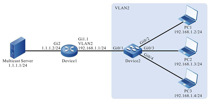
Figure 2-1 Network topology of IGMP snooping
Configuration Steps
Step 1: Device1 configure the interface IP address and enables the multicast route protocol. (omitted)
Step 2: Configure Device2.
#Create VLAN2 on Device2.
|
Device2#configure terminal
Device2(config)#vlan 2
Device2(config-vlan2)#exit
|
#Configure the link type of the port gigabitethernet0/2-gigabitethernet0/4 on Device2 as Access, permitting the services of VLAN2 to pass.
|
Device2(config)#interface gigabitethernet 0/2-0/4
Device2(config-if-range)#switchport access vlan 2
Device2(config-if-range)#exit
|
#Configure the link type of port gigabitethernet0/1 on Device2 as Trunk, permitting the services of VLAN2 to pass; PVID is configured as 1.
|
Device2(config)#interface gigabitethernet 0/1
Device2(config-if-gigabitethernet0/1)#switchport mode trunk
Device2(config-if-gigabitethernet0/1)#switchport trunk allowed vlan add 2
Device2(config-if-gigabitethernet0/1)#switchport trunk pvid vlan 1
Device2(config-if-gigabitethernet0/1)#exit
|
#Enable dropping unknown multicast in VLAN2.
|
Device2(config)#vlan 2
Device2(config-vlan2)#l2-multicast drop-unknown
Device2(config-vlan2)#l3-multicast drop-unknown
Device2(config-vlan2)#exit
|
#Enable IGMP snooping.
|
Device2(config)#ip igmp snooping
Device2(config)#ip igmp snooping vlan 2
|
Step 3: Check the result.
# PC1 and PC2 send IGMPv2 member report packet to add multicast group 224.1.1.1. #View the multicast member table of Device2.
Device2#show ip igmp snooping groups
VLAN ID Interface Name Group Address Expires   Last Reporter  V1 Expires  V2 Expires  Uptime
------- -------------- ------------- -------   -------------  ----------  ----------  -------
2       gi0/2          224.1.1.1     00:03:26  192.168.1.2    stopped                 00:00:55
2       gi0/3          224.1.1.1     00:03:44  192.168.1.3    stopped                 00:00:40
#Multicast Server sends the multicast service packet with destination address 224.1.1.1; PC1 and PC2 can correctly receive the multicast service packet; PC3 cannot receive the multicast service packet.
 Switch


