Network Requirements
- On device2, PC1 and PC2 are isolated from each other in different VLANs.
- Configure the N:1 VLAN mapping function on Device1 to realize the transmission of PC1 and PC2 service packets in the same VLAN when passing through Device1, so as to save VLAN resources.
Network Topology
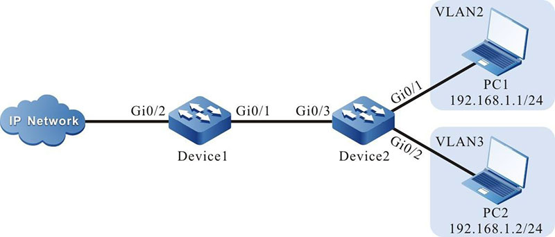
Figure 4-4 Configuring N:1 VLAN Mapping
Configuration Steps
Step 1: Configure Device1.
#Create VLAN2-VLAN4 on Device1.
|
Device1#configure terminal
Device1(config)#vlan 2-4
|
#On Device1, configure the link type of port gigabitethernet0/1 to Trunk and allow services of VLAN2 and VLAN100 to pass, and set PVID to 1.
|
Device1(config)#interface gigabitethernet 0/1
Device1(config-if-gigabitethernet0/1)#switchport mode trunk
Device1(config-if-gigabitethernet0/1)#switchport trunk allowed vlan add 2-4
Device1(config-if-gigabitethernet0/1)#switchport trunk pvid vlan 1
|
#Configure the N:1 VLAN mapping function on the port gigabitothernet0 / 1 of Device1 to map VLAN2 and VLAN3 to vlan4.
|
Device1(config-if-gigabitethernet0/1)#vlan dot1q-tunnel mapping n-to-1 enable
Device1(config-if-gigabitethernet0/1)#vlan dot1q-tunnel mapping n-to-1 2-3 4
Device1(config-if-gigabitethernet0/1)#exit
|
#Configure the link type of port gigabitethernet0/2 on Device1 as trunk, which allows vlan2 - vlan4 services to pass through, and the PVID is configured as 1.
Device1(config)#interface gigabitethernet 0/2
Device1(config-if-gigabitethernet0/2)#switchport mode trunk
Device1(config-if-gigabitethernet0/2)#switchport trunk allowed vlan add 2-4
Device1(config-if-gigabitethernet0/2)#switchport trunk pvid vlan 1
Device1(config-if-gigabitethernet0/2)#exit
|
Step 2: Configure Device2.
#Create VLAN2 and VLAN3 on Device2.
|
Device2#configure terminal
Device2(config)#vlan 2-3
|
#On Device2, configure the link type of port gigabitethernet0/1 to Access and allow services of VLAN2 to pass.
|
Device2(config)#interface gigabitethernet 0/1
Device2(config-if-gigabitethernet0/1)#switchport mode access
Device2(config-if-gigabitethernet0/1)#switchport access vlan 2
Device2(config-if-gigabitethernet0/1)#exit
|
#On Device2, configure the link type of port gigabitethernet0/1 to Access and allow services of VLAN3 to pass.
|
Device2(config)#interface gigabitethernet 0/2
Device2(config-if-gigabitethernet0/2)#switchport mode access
Device2(config-if-gigabitethernet0/2)#switchport access vlan 3
Device2(config-if-gigabitethernet0/2)#exit
|
#On Device2, configure the link type of port gigabitethernet0/1 to Trunk and allow services of VLAN2 and VLAN3 to pass, and configure PVID to 1.
|
Device2(config)#interface gigabitethernet 0/3
Device2(config-if-gigabitethernet0/3)#switchport mode trunk
Device2(config-if-gigabitethernet0/3)#switchport trunk allowed vlan add 2-3
Device2(config-if-gigabitethernet0/3)#switchport trunk pvid vlan 1
Device2(config-if-gigabitethernet0/3)#exit
|
Step 3: Check the result.
#On Device1, query the entry information of N:1 VLAN mapping.
Device1#show vlan dot1q-tunnel mapping n-to-1 configuration
---  ---------------  --------  -----------------  -----------------------------------
NO.  Name             Status    Customer Member    Service VLAN
---  ---------------  --------  -----------------  -----------------------------------
1    gi0/1            enable    2-3                 4
#On Device2, the services of PC1 and PC2 are isolated from each other, the service packets of PC1 are transmitted in VLAN2, and the service packets of PC2 are transmitted in VLAN3.
#The service packets of PC1 and PC2 accessing IP Network are forwarded through VLAN4 of Device1.
 Switch


