Network Requirements
- PC1 accesses PC2 via Device1, Device2, and Device3 in the network environment; the response packet of PC2 reaches PC1 via Device3 and Device1.
- Configure the URPF loose mode on Device3.
- PC1 simulates the attacker to send the invalid packet with the false source address to access PC2. The URPF function of Device3 drops the packet.
Network Topology
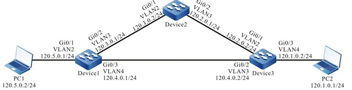
Figure 16-2 Networking of configuring the URPF loose mode
Configuration Steps
Step 1: Configure VLAN and add the port to the corresponding VLAN. (Omitted)
Step 2: Configure the IP address of the interface.(Omitted)
Step 3: Configure the static route in the network, making PC1 access PC2 via Device1, Device2, and Device3; the response packet of PC2 reaches PC1 via Device3 and Device1.
#Configure the static route of Device1, Device2, and Device3; construct the network environment in the network requirements.
|
Device1#configure terminal
Device1(config)#ip route 120.1.0.0 255.255.255.0 120.3.0.2
Device1(config)#ip route 120.2.0.0 255.255.255.0 120.3.0.2
Device2#configure terminal
Device2(config)#ip route 120.1.0.0 255.255.255.0 120.2.0.2
Device3#configure terminal
Device3(config)#ip route 120.5.0.0 255.255.255.0 120.4.0.1
|
#View the route tables of Device1, Device2, and Device3.
Device1#show ip route
Codes: C - connected, S - static, R - RIP, O - OSPF, OE-OSPF External, M - Management
       D - Redirect, E - IRMP, EX - IRMP external, o - SNSP, B - BGP, i-ISIS

Gateway of last resort is not set

S 120.1.0.0/24 [1/10] via 120.3.0.2, 00:10:49, vlan3
S 120.2.0.0/24 [1/10] via 120.3.0.2, 00:11:19, vlan3
C 120.3.0.0/24 is directly connected, 00:19:15, vlan3
C 120.4.0.0/24 is directly connected, 00:15:00, vlan4
C 120.5.0.0/24 is directly connected, 00:07:36, vlan2
C 127.0.0.0/8 is directly connected, 357:23:02, lo0

Device2#show ip route
Codes: C - connected, S - static, R - RIP, O - OSPF, OE-OSPF External, M Management
       D - Redirect, E - IRMP, EX - IRMP external, o - SNSP, B BGP, i-ISIS

Gateway of last resort is not set

S 120.1.0.0/24 [1/10] via 120.2.0.2, 00:15:37, vlan3
C 120.2.0.0/24 is directly connected, 00:17:17, vlan3
C 120.3.0.0/24 is directly connected, 00:25:21, vlan2
C 127.0.0.0/8 is directly connected, 00:38:29, lo0

Device3#show ip route
Codes: C - connected, S - static, R - RIP, O - OSPF, OE-OSPF External, M Management
       D - Redirect, E - IRMP, EX - IRMP external, o - SNSP, B BGP, i-ISIS

Gateway of last resort is not set

C 120.1.0.0/24 is directly connected, 00:17:01, vlan4
C 120.2.0.0/24 is directly connected, 00:19:13, vlan2
C 120.4.0.0/24 is directly connected, 00:18:50, vlan3
S 120.5.0.0/24 [1/10] via 120.4.0.1, 00:17:19, vlan3
C 127.0.0.0/8 is directly connected, 00:26:16, lo0
Step 4: Configure the URPF loose mode on Device3.
#Enable the URPF function on Device3 and configure the URPF loose mode on port gigabitethernet0/1.
|
Device3#configure terminal
Device3(config)#ip urpf
Device3(config)#interface gigabitethernet 0/1
Device3(config-if-gigabitethernet0/1)#ip urpf loose
Device3(config-if-gigabitethernet0/1)#exit
|
Step 5: Check the result.
#PC1 ping PC2
The ping request packet of PC1 reaches PC2 via Device1, Device2, and Device3; the ping response packet of PC2 reaches PC1 via Device3 and Device1.
#PC1 accesses PC2 and the source address is 120.5.0.2.
There is the route to 120.5.0.2 on Device3 and the route egress interface is VLAN3. The route egress interface to the source address VLAN3 and the interface for receiving the packet VLAN2 are not the same interface, but after the URPF loose check, the packet is forwarded by Device3, PC1 can access PC2 and the response packet of PC2 reaches PC1 via Device3 and Device1.
#PC1 simulates the attacker to send the invalid packet with the false source address to access PC2 and the source address is 120.10.0.2.
There is no route to 120.10.0.2 on Device3; URPF drops the packet; PC1 cannot access PC2.

-
The packet dropping generated by the detection does not generate the log or statistics information.
- The difference of the URPF strict and loose modes: In the loose mode, URPF performs the route table searching for the source IP address of the received packet. If finding the route, permit the packet to pass, while in the strict mode, we not only need to find the route, but also the egress interface and the packet receiving interface need to be the same so that the packet can be permitted to pass.
- Usually apply the strict mode. The loose mode is applied to the network environment of the similar case “The coming route and the back route are inconsistent”.
 Switch


