Network Requirements
- RIPv2 runs between Device1, Device2, Device3, and Device4.
- Device1 learns route 200.0.0.0/24 from both Device2 and Device3.
- On Device1, set the route metric offset in the receive direction so that Device1 selects the route advertised by Device2 with priority.
Network Topology
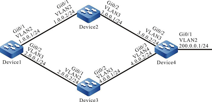
Figure 5-3 Networking for configuring the RIP Metric Offset
Configuration Steps
Step 1: Create VLANs, and add ports to the required VLANs. (Omitted)
Step 2: Configure IP addresses for the ports. (Omitted)
Step 3: Configure RIP.
#Configure Device1.
|
Device1#configure terminal
Device1(config)#router rip
Device1(config-rip)#version 2
Device1(config-rip)#network 1.0.0.0
Device1(config-rip)#network 2.0.0.0
Device1(config-rip)#exit
|
#Configure Device2.
|
Device2#configure terminal
Device2(config)#router rip
Device2(config-rip)#version 2
Device2(config-rip)#network 1.0.0.0
Device2(config-rip)#network 3.0.0.0
Device2(config-rip)#exit
|
#Configure Device3.
|
Device3#configure terminal
Device3(config)#router rip
Device3(config-rip)#version 2
Device3(config-rip)#network 2.0.0.0
Device3(config-rip)#network 4.0.0.0
Device3(config-rip)#exit
|
#Configure Device4.
|
Device4#configure terminal
Device4(config)#router rip
Device4(config-rip)#version 2
Device4(config-rip)#network 3.0.0.0
Device4(config-rip)#network 4.0.0.0
Device4(config-rip)#network 200.0.0.0
Device4(config-rip)#exit
|
#Query the routing table of Device1.
Device1#show ip route
Codes: C - Connected, L - Local, S - static, R - RIP, B - BGP, i-ISIS
       U - Per-user Static route
       O - OSPF, OE-OSPF External, M - Management, E - IRMP, EX - IRMP external

C 1.0.0.0/24 is directly connected, 00:23:06, vlan2
C 2.0.0.0/24 is directly connected, 00:22:56, vlan3
R 3.0.0.0/24 [120/1] via 1.0.0.2, 00:13:26, vlan2
R 4.0.0.0/24 [120/1] via 2.0.0.2, 00:11:04, vlan3
C 127.0.0.0/8 is directly connected, 76:51:00, lo0
R 200.0.0.0/24 [120/2] via 1.0.0.2, 00:08:31, vlan2
               [120/2] via 2.0.0.2, 00:08:31, vlan3
According to the routing table of Device1, two routes to 200.0.0.0/24 are available.
Step 4: Configure the ACL.
#Configure Device1.
|
Device1(config)#ip access-list standard 1
Device1(config-std-nacl)#permit 200.0.0.0 0.0.0.255
Device1(config-std-nacl)#commit
Device1(config-std-nacl)#exit
|
Step 5: Configure a metric offset.
#On Device1, configure the metric offset list and increase the metric of the route that has been learnt from interface VLAN3 and matches AL to 3.
|
Device1(config)#router rip
Device1(config-rip)#offset-list 1 in 3 vlan3
Device1(config-rip)#exit
|
Step 6: Check the result.
#Query the routing table of Device1.
Device1#show ip route
Codes: C - Connected, L - Local, S - static, R - RIP, B - BGP, i-ISIS
       U - Per-user Static route
       O - OSPF, OE-OSPF External, M - Management, E - IRMP, EX - IRMP external

C 1.0.0.0/24 is directly connected, 00:33:59, vlan2
C 2.0.0.0/24 is directly connected, 00:33:50, vlan3
R 3.0.0.0/24 [120/1] via 1.0.0.2, 00:24:20, vlan2
R 4.0.0.0/24 [120/1] via 2.0.0.2, 00:21:57, vlan3
C 127.0.0.0/8 is directly connected, 77:01:54, lo0
R 200.0.0.0/24 [120/2] via 1.0.0.2, 00:19:25, vlan2
According to the routing table of Device1, the next-hop output interface of route 200.0.0.0/24 is only VLAN2, indicating that Device1 has selected the route advertised by Device2 with priority.

-
The route metric offset list can be applied to all interfaces or a specified interface, and it can be used in both the receive and advertisement directions.
 Switch


