Network Requirements
- Four devices in the network are in the same MST domain. Device1 and Device2 convergence layer devices, while Device3 and Device4 are access layer devices.
- To reasonably balance traffic on the links to realize load sharing and redundancy backup, configure packets of VLAN2 to be forwarded following instance 1. The root bridge of instance 1 is Device1. Packets of VLAN3 are forwarded following instance 2. The root bridge of instance 2 is Device2. Packets of VLAN4 are forwarded following instance 0.
Network Topology
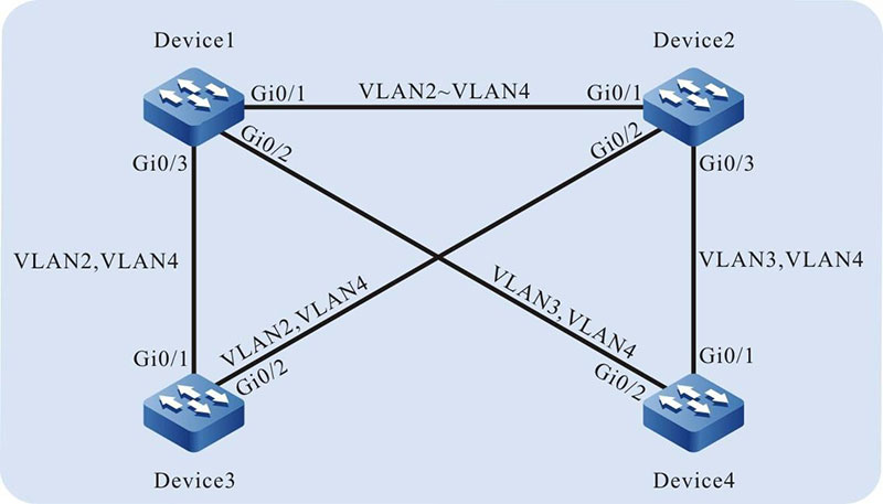
Figure 9-1 Networking for MSTP Typical Application
Configuration Steps
Step 1: Configure VLANs, and configure the link type of the ports.
#On Device1, create VLAN2-VLAN4, configure the link type of port gigabitethernet0/1 to Trunk and allow services of VLAN2-VLAN4 to pass.
|
Device1(config)#vlan 2-4 Device1(config)#interface gigabitethernet 0/1
Device1(config-if-gigabitethernet0/1)#switchport mode trunk
Device1(config-if-gigabitethernet0/1)#switchport trunk allowed vlan add 2-4
Device1(config-if-gigabitethernet0/1)#exit
|
#On Device1, configure the link type of port gigabitethernet0/2 to Trunk and allow services of VLAN3 and VLAN4 to pass. Configure the link type of port gigabitethernet0/3 to Trunk and allow services of VLAN2 and VLAN4 to pass. (Omitted)
#On Device2, create VLAN2-VLAN4. Configure the link type of ports gigabitethernet0/1- gigabitethernet0/3 to Trunk, configure gigabitethernet0/1 to allow services of VLAN2- VLAN4 to pass, gigabitethernet0/2 to allow services of VLAN2 and VLAN4 to pass, and gigabitethernet0/3 to allow services of VLAN3 and VLAN4 to pass. (Omitted)
#On Device3, create VLAN2-VLAN4, configure the link type of port gigabitethernet0/1- gigabitethernet0/2 to Trunk and allow services of VLAN2-VLAN4 to pass. (Omitted)
#On Device4, create VLAN3 and VLAN4, configure the link type of port gigabitethernet0/1-gigabitethernet0/2 to Trunk and allow services of VLAN3 and VLAN4 to pass. (Omitted)
Step 2: Configure an MST region.
#On Device1, configure an MST region. Set the domain name to admin, the revision level to 1, map instance 1 to VLAN2, map instance 2 to VLAN3, and activate the MST region.
|
Device1#configure terminal
Device1(config)#spanning-tree mst configuration
Device1(config-mst)#region-name admin
Device1(config-mst)#revision-level 1
Device1(config-mst)#instance 1 vlan 2
Device1(config-mst)#instance 2 vlan 3
Device1(config-mst)#active configuration pending
Device1(config-mst)#exit
|

-
The MST region configuration of Device2, Device3, and Device 4 is far different from that of Device1. (Omitted)
#On Device1, configure the priority of MSTI 1 to 0. On Device2, configure the priority of MSTI 2 to 0.
|
Device1(config)#spanning-tree mst instance 1 priority 0
Device2(config)#spanning-tree mst instance 2 priority 0
|
#On Device1, enable the spanning tree globally.
|
Device1(config)#spanning-tree enable
|
-
The configuration for enabling the spanning tree globally on Device2, Device3, and Device 4 is far different from that on Device1. (Omitted)
Step 3: Check the result.
#After the network topology is stable, check the calculation result of all spanning tree instances.
Device1#show spanning-tree mst
Spanning-tree enabled protocol mstp
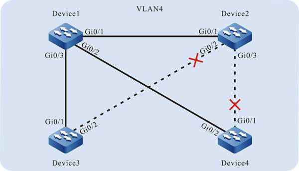
MST Instance 00 vlans mapped: 1,4-4094
Bridge address 0000.0000.008b priority 32768
Region root address 0000.0000.008b priority 32768
Designated root address 0000.0000.008b priority 32768
root: 0, rpc: 0, epc: 0, hop: 20
Operational hello time 2, forward time 15, max age 20
Configured hello time 2, forward time 15, max age 20, max hops 20, hold count 6
Flap guard : admin false, max count 5, detect period 10s, recovery period 30s
Tc protection: admin true, threshold 3, interval 2s, rxTcCnt 0, status:NORMAL
Bpdu length-check: false, bpdu illegal length packets count: 0
Autoedge swap-check: true
Swap-delay time: 30
Configured timer factor: 3
Topology Change Count:4, last change occured:0 hour 1 minute 0 second(60 seconds)
Interface Role Sts Cost Prio.Nbr Type
------------------------------------------------------------------
gi0/1 Desg FWD 20000 128.001 P2P
gi0/2 Desg FWD 20000 128.002 P2P
gi0/3 Desg FWD 20000 128.003 P2P
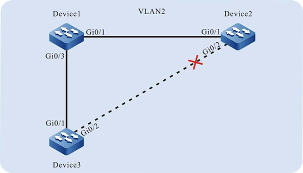
MST Instance 01 vlans mapped: 2
Bridge ID address 0000.0000.008b priority 1/0
Designated root address 0000.0000.008b priority 1
root: 0, rpc: 0, hop: 20
Topology Change Count:4, last change occured:0 hour 1 minute 0 second(60 seconds)
Interface Role Sts Cost Prio.Nbr Type
-----------------------------------------------------------------
gi0/1 Desg FWD 20000 128.001 P2P
gi0/3 Desg FWD 20000 128.003 P2P
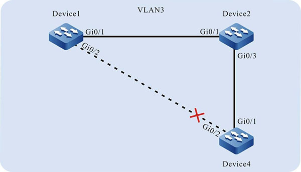
MST Instance 02 vlans mapped: 3
Bridge ID address 0000.0000.008b priority 32770/32768
Designated root address 0001.7a54.5c96 priority 2
root: 32769, rpc: 20000, hop: 19
Topology Change Count:4, last change occured:0 hour 1 minute 0 second(60 seconds)
Interface Role Sts Cost Prio.Nbr Type
---------------------------------------------------------------=
gi0/1 Root FWD 20000 128.001 P2P
gi0/2 Desg FWD 20000 128.002 P2P
#On Device2, query the calculation result of all spanning tree instances. According to the result, port gigabitethernet0/2 of Device2 is blocked in both instance 0 and instance 1.
Device2#show spanning-tree mst
Spanning-tree enabled protocol mstp
MST Instance 00        vlans mapped: 1,4-4094
 Bridge                address 0001.7a54.5c96 priority 32768
 Region root           address 0000.0000.008b priority 32768
 Designated root       address 0000.0000.008b priority 32768
                        root: 32769, rpc: 20000, epc: 0, hop: 19
 Operational hello time 2, forward time 15, max age 20
 Configured hello time 2, forward time 15, max age 20, max hops 20, hold count 6
 Flap guard : admin false, max count 5, detect period 10s, recovery period 30s
 Tc protection: admin true, threshold 3, interval 2s, rxTcCnt 0, status:NORMAL
 Bpdu length-check: false, bpdu illegal length packets count: 0
 Autoedge swap-check: true
 Swap-delay time: 30
 Configured timer factor: 3
 Topology Change Count:4, last change occured:0 hour 1 minute 0 second(60 seconds)
           Interface Role Sts      Cost     Prio.Nbr Type
gi0/1                 Root  FWD    20000    128.001  P2P
gi0/2                 Alte DIS     20000    128.002  P2P
gi0/3                 Desg FWD     20000    128.003  P2P
MST Instance 01        vlans mapped: 2
 Bridge ID            address 0001.7a54.5c96 priority 32769/32768
 Designated root      address 0000.0000.008b priority 1
                        root: 32769, rpc: 20000, hop: 19
Topology Change Count:4, last change occured:0 hour 1 minute 0 second(60 seconds)
           Interface Role Sts     Cost   Prio.Nbr Type
---------------------------------------------------------
gi0/1                 Root FWD    20000  128.001  P2P
gi0/2                 Alte DIS    20000  128.002  P2P
MST Instance 02        vlans mapped: 3
 Bridge ID            address 0001.7a54.5c96 priority 2/0
 Designated root      address 0001.7a54.5c96 priority 2
                        root: 0, rpc: 0, hop: 20
Topology Change Count:4, last change occured:0 hour 1 minute 0 second(60 seconds)
           Interface  Role Sts     Cost   Prio.Nbr Type
----------------------------------------------------------
gi0/1                 Desg  FWD    20000   128.001 P2P
gi0/3                 Desg FWD     20000   128.003 P2P
#On Device3, query the calculation result of all spanning tree instances.
Device3#show spanning-tree mst
Spanning-tree enabled protocol mstp
MST Instance 00        vlans mapped: 1,4-4094
 Bridge                address 0000.0305.070a priority 32768
 Region root           address 0000.0000.008b priority 32768
 Designated root       address 0000.0000.008b priority 32768
                        root: 32769, rpc: 20000, epc: 0, hop: 19
 Operational hello time 2, forward time 15, max age 20
 Configured hello time 2, forward time 15, max age 20, max hops 20, hold count 6
 Flap guard : admin false, max count 5, detect period 10s, recovery period 30s
 Tc protection: admin true, threshold 3, interval 2s, rxTcCnt 0, status:NORMAL
 Bpdu length-check: false, bpdu illegal length packets count: 0
 Autoedge swap-check: true
 Swap-delay time: 30
 Configured timer factor: 3
 Topology Change Count:4, last change occured:0 hour 1 minute 0 second(60 seconds)
           Interface Role Sts      Cost   Prio.Nbr Type
-----------------------------------------------------------
gi0/1                 Root FWD     20000   128.001 P2P
gi0/2                 Desg FWD     20000   128.002 P2P
MST Instance 01        vlans mapped: 2
 Bridge ID            address 0000.0305.070a priority 32769/32768
 Designated root      address 0000.0000.008b priority 1
                        root: 32769, rpc: 20000, hop: 19
Topology Change Count:4, last change occured:0 hour 1 minute 0 second(60 seconds)
           Interface Role Sts     Cost    Prio.Nbr Type
-------------------------------------------------------
gi0/1                 Root FWD    20000   128.001 P2P
gi0/2                 Desg FWD    20000   128.002 P2P
#On Device4, query the calculation result of all spanning tree instances. According to the result, port gigabitethernet0/1 of Device4 is blocked in instance 0, and port gigabitethernet0/2 is blocked in instance 2.
Device4#show spanning-tree mst
Spanning-tree enabled protocol mstp
MST Instance 00        vlans mapped: 1,4-4094
 Bridge                address 0001.7a58.dc0c priority 32768
 Region root           address 0000.0000.008b priority 32768
 Designated root       address 0000.0000.008b priority 32768
                        root: 32769, rpc: 20000, epc: 0, hop: 19
 Operational hello time 2, forward time 15, max age 20
 Configured hello time 2, forward time 15, max age 20, max hops 20, hold count 6
 Flap guard : admin false, max count 5, detect period 10s, recovery period 30s
 Tc protection: admin true, threshold 3, interval 2s, rxTcCnt 0, status:NORMAL
 Bpdu length-check: false, bpdu illegal length packets count: 0
 Autoedge swap-check: true
 Swap-delay time: 30
 Configured timer factor: 3
 Topology Change Count:4, last change occured:0 hour 1 minute 0 second(60 seconds)
           Interface Role Sts     Cost     Prio.Nbr Type
-----------------------------------------------------------
gi0/1                 Alte DIS     20000   128.001 P2P
gi0/2                 Root FWD     20000   128.002 P2P
MST Instance 02        vlans mapped: 3
 Bridge ID            address 0001.7a58.dc0c priority 32770/32768
 Designated root      address 0001.7a54.5c96 priority 2
                        root: 32769, rpc: 20000, hop: 19
Topology Change Count:4, last change occured:0 hour 1 minute 0 second(60 seconds)
           Interface Role Sts     Cost    Prio.Nbr Type
---------------------------------------------------------
gi0/1                 Root FWD    20000   128.001 P2P
gi0/2                 Alte DIS    20000   128.002 P2P
Based on the spanning tree calculation result of the four devices, the tree diagrams corresponding to MSTI 0 (mapped to VLAN4), MSTI 1 (mapped to VLAN2), and MSTI 2 (mapped to VLAN3) are obtained.
 Switch


