Network Requirements
- Enable the authentication on the interface to enable the devices configured with the same password establishing the neighbor relationship.
- Device1 is the Level-1 router, Device2 is the Level-1-2 router, and Device1 and Device2 are in the same area, Area 10. Device3 is the Level-2 router in Area 20. Device2 connects the two areas.
Network Topology
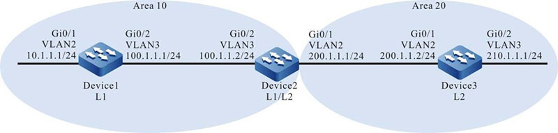
Figure 9–5 Networking of the IS-IS neighbor authentication
Configuration Steps
Step 1: Configure the IP address of the interfaces. (Omitted)
Step 2: Configure the IS-IS and enable the process on the interface.
#Configure the IS-IS process as 100, area number as 10, and type as Level-1 and enable the process on the interface on Device1.
|
Device1#configure terminal
Device1(config)#router isis 100
Device1(config-isis)#net 10.0000.0000.0001.00
Device1(config-isis)#is-type level-1
Device1(config-isis)#metric-style wide
Device1(config-isis)#exit
Device1(config)#interface vlan2
Device1(config-if-vlan2)#ip router isis 100
Device1(config-if-vlan2)#exit
Device1(config)#interface vlan3
Device1(config-if-vlan3)#ip router isis 100
Device1(config-if-vlan3)#exit
|
#Configure the IS-IS process as 100, area number as 10, and type as Level-1-2 and enable the process on the interface on Device2.
|
Device2#configure terminal
Device2(config)#router isis 100
Device2(config-isis)#net 10.0000.0000.0002.00
Device2(config-isis)#metric-style wide
Device2(config-isis)#exit
Device2(config)#interface vlan2
Device2(config-if-vlan2)#ip router isis 100
Device2(config-if-vlan2)#exit
Device2(config)#interface vlan3
Device2(config-if-vlan3)#ip router isis 100
Device2(config-if-vlan3)#exit
|
#Configure the IS-IS process as 100, area number as 20, and type as Level-2 and enable the process on the interface on Device3.
|
Device3#configure terminal
Device3(config)#router isis 100
Device3(config-isis)#net 20.0000.0000.0003.00
Device3(config-isis)#is-type level-2
Device3(config-isis)#metric-style wide
Device3(config-isis)#exit
Device3(config)#interface vlan2
Device3(config-if-vlan2)#ip router isis 100
Device3(config-if-vlan2)#exit
Device3(config)#interface vlan3
Device3(config-if-vlan3)#ip router isis 100
Device3(config-if-vlan3)#exit
|
#View the IS-IS neighboring information of Device1.
Device1#show isis neighbors
IS-IS Instance 100 Neighbors (Counter 1):
Type   System ID      Interface  State Holdtime Level IETF-NSF Priority Circuit ID
L1-LAN 0000.0000.0002 vlan3      Up    29 sec   L1    capable  64       0000.0000.0001.01
#View the IS-IS neighboring information on Device2.
Device2#show isis neighbors
IS-IS Instance 100 Neighbors (Counter 2):
Type   System ID      Interface  State Holdtime Level IETF-NSF Priority Circuit ID
L2-LAN 0000.0000.0003 vlan2      Up    9 sec    L2    capable  64       0000.0000.0003.01
L1-LAN 0000.0000.0001 vlan3      Up    7 sec    L1    capable  64       0000.0000.0001.01
#View the IS-IS neighboring information of Device3.
Device3#show isis neighbors
IS-IS Instance 100 Neighbors (Counter 1):
Type   System ID      Interface  State Holdtime Level IETF-NSF Priority Circuit ID
L2-LAN 0000.0000.0002 vlan2      Up    24 sec   L2    capable  64       0000.0000.0003.01
Step 3: Configure the authentication.
#Configure the MD5 authentication and password admin on the interface of Device2.
|
Device2(config)#interface vlan2
Device2(config-if-vlan2)#isis authentication mode md5
Device2(config-if-vlan2)#isis authentication key 0 admin
Device2(config-if-vlan2)#exit
Device2(config)#interface vlan3
Device2(config-if-vlan3)#isis authentication mode md5
Device2(config-if-vlan3)#isis authentication key 0 admin
Device2(config-if-vlan3)#exit
|
#View the IS-IS neighbor of Device2.
Device2#show isis neighbors
IS-IS Instance 100 Neighbors (Counter 0):
Type System ID     Interface    State Holdtime Level IETF-NSF Priority Circuit ID
At this time, Device1 and Device3 are not configured with the authentication. Device2 does not establish the IS-IS neighbor.
#Configure the MD5 authentication and password admin on the valn3 interface of Device1.
|
Device1(config)#interface vlan3
Device1(config-if-vlan3)#isis authentication mode md5
Device1(config-if-vlan3)#isis authentication key 0 admin
Device1(config-if-vlan3)#exit
|
#Configure the MD5 authentication and password admin on the valn2 interface of Device3.
|
Device3(config)#interface vlan2
Device3(config-if-vlan2)#isis authentication mode md5
Device3(config-if-vlan2)#isis authentication key 0 admin
Device3(config-if-vlan2)#exit
|
Step 4: Check the result.
#View the IS-IS neighboring information of Device1.
Device1#show isis neighbors
IS-IS Instance 100 Neighbors (Counter 1):
Type   System ID      Interface State Holdtime Level IETF-NSF Priority Circuit ID
L1-LAN 0000.0000.0002 vlan3     Up    29 sec   L1    capable  64       0000.0000.0001.01
It can be observed that the IS-IS neighbor is successfully established between Device1 and Device2. It indicates that the authentication succeeds.
#View the IS-IS neighboring information on Device2.
Device2#show isis neighbors
IS-IS Instance 100 Neighbors (Counter 2):
Type   System ID      Interface  State Holdtime Level IETF-NSF Priority Circuit ID
L2-LAN 0000.0000.0003 vlan2      Up    9 sec    L2    capable  64       0000.0000.0003.01
L1-LAN 0000.0000.0001 vlan3      Up    7 sec    L1    capable  64       0000.0000.0001.01
It can be observed that the IS-IS neighbor is successfully established between Device2 and Device1/Device3. It indicates that the authentication succeeds.
#View the IS-IS neighboring information of Device3.
Device3#show isis neighbors
IS-IS Instance 100 Neighbors (Counter 1):
Type   System ID      Interface  State Holdtime Level IETF-NSF Priority Circuit ID
L2-LAN 0000.0000.0002 vlan2      Up    24 sec   L2    capable  64       0000.0000.0003.01
It can be observed that the IS-IS neighbor is successfully established between Device3 and Device2. It indicates that the authentication succeeds.
#View the routing information of Device2. Device2 can normally receives the routing advertised by Device1 and Device3.
Device2#show ip route
Codes: C - connected, S - static, R - RIP, O - OSPF, OE-OSPF External, M - Management
       D - Redirect, E - IRMP, EX - IRMP external, o - SNSP, B - BGP, i-IS-IS

Gateway of last resort is not set

i 10.1.1.0/24 [115/20] via 100.1.1.1, 16:58:26, vlan3
C 100.1.1.0/24 is directly connected, 18:39:58, vlan3
C 127.0.0.0/8 is directly connected, 20:16:34, lo0
C 200.1.1.0/24 is directly connected, 18:39:37, vlan2
i 210.1.1.0/24 [115/20] via 200.1.1.2, 16:57:56, vlan2

Device2#show isis ipv4 route
IS-IS Instance 100, VRF Kernel, IPv4 routes table (Counter 4):
L1 10.1.1.0/24, flags none, metric 20, from learned, installed
     via 100.1.1.1, vlan3, neighbor 0000.0000.0001
L1 100.1.1.0/24, flags none, metric 10, from network connected
     via 0.0.0.0, vlan3
L1 200.1.1.0/24, flags none, metric 10, from network connected
     via 0.0.0.0, vlan2
L2 210.1.1.0/24, flags none, metric 20, from learned, installed
     via 200.1.1.2, vlan2, neighbor 0000.0000.0003
 Switch


