Network Requirements
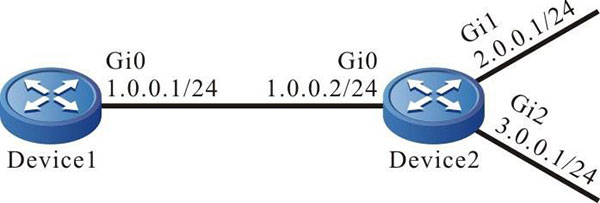
- The IRMP operated between Device1 and Device2 for routing interaction.
- Device1 learns two routing 2.0.0.0/24 and 3.0.0.0/24 advertised by Device2 and Device1 only reserves the routing information of 2.0.0.0/24.
Network Topology

Figure 11–4 Networking of the IRMP route filtering
Configuration Steps
Step 1: Configure the IP address of the interfaces. (Omitted)
Step 2: Configure the IRMP.
#Configure Device1.
|
Device1#configure terminal
Device1(config)#router irmp 100
Device1(config-irmp)#network 1.0.0.0 0.0.0.255
Device1(config-irmp)#exit
|
#Configure Device2.
|
Device2#configure terminal
Device2(config)#router irmp 100
Device2(config-irmp)#network 1.0.0.0 0.0.0.255
Device2(config-irmp)#network 2.0.0.0 0.0.0.255
Device2(config-irmp)#network 3.0.0.0 0.0.0.255
Device2(config-irmp)#exit
|
#View the IRMP neighbor inofrmation of Device1.
Device1#show ip irmp neighbor
IP-IRMP neighbors for process 100 Total neighbor 1
Address   Interface          Hold(s) Uptime   SeqNum   Srtt(ms) Rto(s)
1.0.0.2   gigabitethernet0   11      00:05:00 3        0        2
It can be viewed that the IRMP neighbor is successfully established between Device1 and Device2.
#View the routing table of Device1.
Device1#show ip irmp topology
IP-IRMP Topology Table for process 100
Codes: P - Passive, A - Active, H - Holddown, D - Hidden
        > - FIB route, * - FIB successor

P >1.0.0.0/24, 1 successors, FD is 2816
        *via Connected (2816/0), gigabitethernet0
P >2.0.0.0/24, 1 successors, FD is 3072
        *via 1.0.0.2 (3072/2816), gigabitethernet0
P >3.0.0.0/24, 1 successors, FD is 3072
        *via 1.0.0.2 (3072/2816), gigabitethernet0

Device1#show ip route
Codes: C - connected, S - static, R - RIP, O - OSPF, OE-OSPF External, M - Management
       D - Redirect, E - IRMP, EX - IRMP external, o - SNSP, B - BGP, i-ISIS

Gateway of last resort is not set

C 1.0.0.0/24 is directly connected, 00:11:29, gigabitethernet0
E 2.0.0.0/24 [90/3072] via 1.0.0.2, 00:07:43, gigabitethernet0
E 3.0.0.0/24 [90/3072] via 1.0.0.2, 00:07:40, gigabitethernet0
C 127.0.0.0/8 is directly connected, 00:19:50, lo0
Device1 learns the routing 2.0.0.0/24 and 3.0.0.0/24.
Step 3: Configure the route filtering.
#Configure the ACL rule to only permit the routing 2.0.0.0/24 on Device1 and configure the inbound filtering list to coordinate with the ACL in the IRMP.
|
Device1(config)#ip access-list standard 1
Device1(config-std-nacl)#permit 2.0.0.0 0.0.0.255
Device1(config-std-nacl)#exit
Device1(config)#router irmp 100
Device1(config-irmp)#distribute-list 1 in
Device1(config-irmp)#exit
|

-
When configuring the route filtering, the prefix list and ACL can establish the matching rule. The difference lies in that the prefix list can accurately match the route mask, but the ACL cannot match the route mask.
Step 4: Check the result.
#View the topology table and routing table of Device1.
Device1#show ip irmp topology
IP-IRMP Topology Table for process 100
Codes: P - Passive, A - Active, H - Holddown, D - Hidden
        > - FIB route, * - FIB successor

P >1.0.0.0/24, 1 successors, FD is 2816
        *via Connected (2816/0), gigabitethernet0
P >2.0.0.0/24, 1 successors, FD is 3072
        *via 1.0.0.2 (3072/2816), gigabitethernet0

Device1#show ip route
Codes: C - connected, S - static, R - RIP, O - OSPF, OE-OSPF External, M - Management
       D - Redirect, E - IRMP, EX - IRMP external, o - SNSP, B - BGP, i-ISIS

Gateway of last resort is not set

C 1.0.0.0/24 is directly connected, 00:22:33, gigabitethernet0
E 2.0.0.0/24 [90/3072] via 1.0.0.2, 00:04:18, gigabitethernet0
C 127.0.0.0/8 is directly connected, 00:30:55, lo0
Device1 only learns the routing 2.0.0.0/24, but the routing 3.0.0.0/24 is successfully filtered.

-
Configuring the distribute-list command may cause the IRMP neighbor to be reestablished.
 Switch
 Wifi - Access Point
 Firewall
 Router
 Module Quang
![Module Quang Cisco]() Module Quang Cisco
Module Quang Cisco![Module quang HPE]() Module quang HPE
Module quang HPE![Module quang Maipu]() Module quang Maipu
Module quang Maipu![Module quang Brocade]() Module quang Brocade
Module quang Brocade![Module quang Fortinet]() Module quang Fortinet
Module quang Fortinet![Module quang Aruba]() Module quang Aruba
Module quang Aruba![Module quang OEM]() Module quang OEM
Module quang OEM![Module quang Juniper]() Module quang Juniper
Module quang Juniper![Module quang Dell]() Module quang Dell
Module quang Dell![Module quang Palo Alto]() Module quang Palo Alto
Module quang Palo Alto![Module quang Huawei]() Module quang Huawei
Module quang Huawei![Module quang Arista]() Module quang Arista
Module quang Arista![Module quang F5]() Module quang F5
Module quang F5![Module quang H3C]() Module quang H3C
Module quang H3C![Module Quang Allied Telesis]() Module Quang Allied Telesis
Module Quang Allied Telesis![Module quang SonicWall]() Module quang SonicWall
Module quang SonicWall![Module quang Mikrotik]() Module quang Mikrotik
Module quang Mikrotik![Module quang Handar]() Module quang Handar
Module quang Handar Máy chủ (Server)
 Thiết bị lưu trữ (SAN, NAS)
 Load Balancing
 Video Conferencing
 Phụ kiện máy chủ
 Thiết Bị IoT
 Phụ Kiện Mạng


.png)


