Network Requirements
- Device1 and Device2 form the stacking system and serve as MVST management device, and Device 3, Device 4, and Device 5 are used as extended cards, and the last two ports of the extended card are connected to the MVST management device;
- Perform the differentiated configuration for Device3, Device4 and Device5, and bind the configuration of the extended cards corresponding to link aggregation 1, link aggregation 2 and link convergence 3 to the MVST management device;
- After simulating the failure of Device3, replace a new device (Device6), and the MVST management device can automatically issue the previously collected Device3 configuration.
- It is simulated that when link aggregation 1 of MVST management device fails, link aggregation 4 needs to be created, and the configuration of Device3 bound to link aggregation group 1 is migrated to link aggregation 4.
Network Topology
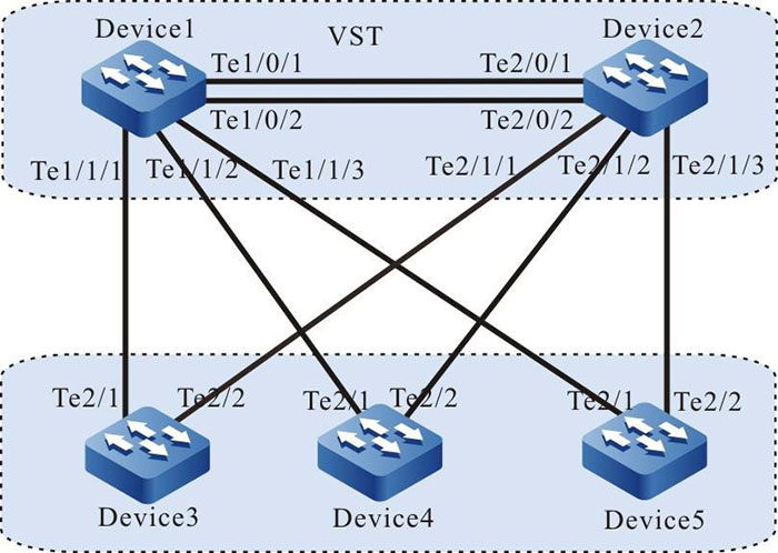
Figure 3-4 Configure auto delivering the bound configuration
Configuration Steps
Step 1: Configure the VST system.
#Configure virtual switch member device number as 1, domain number as 10 and priority as 255 on Device1.
|
Device1#configure terminal
Device1(config)#switch virtual member 1
Do you want to modify member id(Yes|No)?y
% Member ID 1 config will take effect only after the exec command 'switch mode virtual' is issued
Device1(config-vst-member-1)#domain 10
% Domain ID 10 config will take effect only after the exec command 'switch mode virtual' is issued
Device1(config-vst-member-1)#priority 255
Device1(config-vst-member-1)#exit
|
#On Device1, create virtual switch link interface 1, and add ports tentengigabitethernet0/1 and tentengigabitethernet0/2 to virtual switch link interface 1.
|
Device1(config)#vsl-channel 1
Device1(config-vsl-channel-1)#exit
Device1(config)#interface tentengigabitethernet 0/1
Device1(config-if-tentengigabitethernet0/1)#vsl-channel 1 mode on
Device1(config-if-tentengigabitethernet0/1)#exit
Device1(config)#interface tentengigabitethernet 0/2
Device1(config-if-tentengigabitethernet0/2)#vsl-channel 1 mode on
Device1(config-if-tentengigabitethernet0/2)#exit
|
#On Device1, save the configuration.
|
Device1#write
Are you sure to overwrite /flash/startup (Yes|No)?y
Building Configuration...done
Write to startup file... OK
Write to mode file... OK
|
#Configure virtual switch member device number as 2, domain number as 10 and priority as 255 on Device2.
|
Device2#configure terminal
Device2(config)#switch virtual member 2
Do you want to modify member id(Yes|No)?y
% Member ID 2 config will take effect only after the exec command 'switch mode virtual' is issued
Device2(config-vst-member-2)#domain 10
% Domain ID 10 config will take effect only after the exec command 'switch mode virtual' is issued
Device2(config-vst-member-2)#priority 200
Device2(config-vst-member-2)#exit
|
#On Device2, create virtual switch link interface 1, and add ports tentengigabitethernet1/1 to virtual switch link interface 1.
|
Device2(config)#vsl-channel 1
Device2(config-vsl-channel-1)#exit
Device2(config)#interface tentengigabitethernet 0/1
Device2(config-if-tentengigabitethernet0/1)#vsl-channel 1 mode on
Device2(config-if-tentengigabitethernet0/1)#exit
Device2(config)#interface tentengigabitethernet 0/2
Device2(config-if-tentengigabitethernet0/2)#vsl-channel 1 mode on
Device2(config-if-tentengigabitethernet0/2)#exit
|
#On Device2, save the configuration.
|
Device2#write
Are you sure to overwrite /flash/startup (Yes|No)?y
Building Configuration... done
Write to startup file... OK
Write to mode file... OK
|
#Configure the running mode of Device1 as the stacking mode.
|
Device1#switch mode virtual
This command will convert all interface names to naming convention "interface-type member-number/slot/interface",
Please make sure to save current configuration.Do you want to proceed? (yes|no)?y
Converting interface names Building configuration...
Copying the startup configuration to backup file named "startup-backupalone"...
Please wait... system reloading is in progress!
ok
Reset system!
%SYS-5-RELOAD: Reload requested
|
#Configure the running mode of Device2 as the stacking mode.
|
Device2#switch mode virtual
This command will convert all interface names to naming convention "interface-type member-number/slot/interface",
Please make sure to save current configuration.Do you want to proceed? (yes|no)?y
Converting interface names Building configuration...
Copying the startup configuration to backup file named "startup-backupalone"...
Please wait...system reloading is in progress!
ok
Reset system!
%SYS-5-RELOAD: Reload requested
|
#View on Device1, the stacking system is formed, and Device1 is the master device of the stacking system.
Device1#show switch virtual
Codes: L - local-device,I - isolate-device

Virtual Switch Mode        : VIRTUAL Virtual
Switch DomainId            : 10
Virtual Switch mac-address : 0001.7a6a.0255

----------------VST MEMBER INFORMATION----------------------------
CODE MemberID Role     Pri  LocalVsl         RemoteVsl
L    1        Master   255  vsl-channel 1/1  vsl-channel 2/1
     2        Member   200  vsl-channel 2/1  vsl-channel 1/1
Step 2: Configure the MVST basic functions.
#Configure the stacking system as the MVST management device.
|
Device1(config)#mvst enable
%MVST-NOTIFY-5: MVST is enabled !
Device1(config)#mvst master
Device1(config)#mvst domain-name test
|
#Configure the link aggregation of the stacking system, and enable the MVST detection.
|
Device1(config)#mvst link-aggregation 1 mode lacp
Device1(config)# mvst interface tengigabitethernet 1/1/1,2/1/1 join link-aggregation 1 active
Device1(config)#interface link-aggregation 1
Device1(config-link-aggregation1)#mvst inspection
Device1(config-link-aggregation1)#exit
Device1(config)#mvst link-aggregation 2 mode lacp
Device1(config)# mvst interface tengigabitethernet 1/1/2,2/1/2 join link-aggregation 2 active
Device1(config)#interface link-aggregation 2
Device1(config-link-aggregation2)#mvst inspection
Device1(config-link-aggregation2)#exit
Device1(config)#mvst link-aggregation 3 mode lacp
Device1(config)# mvst interface tengigabitethernet 1/1/3,2/1/3 join link-aggregation 3 active
Device1(config)#interface link-aggregation 3
Device1(config-link-aggregation3)#mvst inspection
Device1(config-link-aggregation3)#exit
|
#On Device3, enable the MVST function.
|
Device3#configure terminal
Device3(config)#mvst enable
%MVST-NOTIFY-5: interface tengigabitethernet2/1 and interface tengigabitethernet2/2 join link-aggregation 1 successfully.
%MVST-NOTIFY-5: MVST is enabled !
|
#On Device4, enable the MVST function.
|
Device4#configure terminal
Device4(config)#mvst enable
%MVST-NOTIFY-5: interface tengigabitethernet2/1 and interface tengigabitethernet2/2 join link-aggregation 1 successfully.
%MVST-NOTIFY-5: MVST is enabled !
|
#On Device5, enable the MVST function.
|
Device5#configure terminal
Device5(config)#mvst enable
%MVST-NOTIFY-5: interface tengigabitethernet2/1 and interface tengigabitethernet2/2 join link-aggregation 1 successfully.
%MVST-NOTIFY-5: MVST is enabled !
|
#Connect Device3, Device4, and Device5 to the MVST domain, and then, check the MVST result after the devices are connected.
#Check the MVST results on Device1. You can see that Device3, Device4, and Device5 join the MVST domain in the form of an extended card. The slots are Slave-slot0, Slave-slot1, and Save-slot2, and their host names change to switch-ss0, switch-ss1, and switch-ss2.
Device1#show mvst topo information
-------------------------------------------------------------------------------------------------
role       domain-name  interface           mac             device-type                host-name
-------------------------------------------------------------------------------------------------
Slave-slot test         link-aggregation 1  0001.7a63.bd76  MyPower S4230-52TXF (V1)   switch-ss0
Slave-slot test         link-aggregation 2  0001.7a64.72aa  MyPower S4230-52TXF (V1)   switch-ss1
Slave-slot test         link-aggregation 3  0001.7a63.bd43  MyPower S4230-52TXF (V1)   switch-ss2
Master     test	                            0001.7a6a.0258  MyPower S4230-52TXF (V1)   Device1
Step 3: Configure the function of auto delivering the bound configuration.
#Perform the differentiated configuration for Device3, Device4, and Device5.
|
Device1(config)#configure slave-slot 0
switch-ss0(config)#vlan 100
switch-ss0(config)#exit
switch-ss0#exit
switch-ss0>exit
Device1(config)#configure slave-slot 1
switch-ss1(config)#vlan 200
switch-ss1(config)#exit
switch-ss1#exit
switch-ss1>exit
Device1(config)#configure slave-slot 2
switch-ss2(config)#vlan 300
switch-ss2(config)#exit
switch-ss2#exit
switch-ss2>exit
|
#On Device1, save the configurations of Device3, Device4, and Device5.
|
Device1#write slave-slot 0
Are you sure to overwrite slave slot 0 /flash/startup (Yes|No)?y
Device1#
Jan 9 2015 16:32:34: %MVST-WRITE_RESULT-5: The slave slot 0 write to startup file successfully.
Device1#write slave-slot 1
Are you sure to overwrite slave slot 0 /flash/startup (Yes|No)?y
Device1#
Jan 9 2015 16:32:34: %MVST-WRITE_RESULT-5: The slave slot 1 write to startup file successfully.
Device1#write slave-slot 2
Are you sure to overwrite slave slot 0 /flash/startup (Yes|No)?y
Device1#
Jan 9 2015 16:32:34: %MVST-WRITE_RESULT-5: The slave slot 2 write to startup file successfully.
|
#Configure the function of auto delivering the bound configuration on Device1. The startup of the extended cards corresponding to link aggregation group 1, link aggregation group 2 and link aggregation group 3 is collected to the MVST management device.
|
Device1(config)#mvst bind startup link-aggregation 1
Device1(config)#
Jan 9 2015 15:25:16: %MVST-COLLECT_STARTUP-5: Collect slave slot 0 startup begin.
Jan 9 2015 15:25:16: %MVST-COLLECT_STARTUP-5: Collect slave slot 0 startup OK.
Device1(config)#mvst bind startup link-aggregation 2
Device1(config)#
Jan 9 2015 15:25:16: %MVST-COLLECT_STARTUP-5: Collect slave slot 1 startup begin.
Jan 9 2015 15:25:16: %MVST-COLLECT_STARTUP-5: Collect slave slot 1 startup OK.
Device1(config)#mvst bind startup link-aggregation 3
Device1(config)#
Jan 9 2015 15:25:16: %MVST-COLLECT_STARTUP-5: Collect slave slot 2 startup begin.
Jan 9 2015 15:25:16: %MVST-COLLECT_STARTUP-5: Collect slave slot 2 startup OK.
|
#View the results of auto delivering the bound configuration on Device1. The startup of extended cards 0, 1 and 2 are collected into the startup-lag1, startup-lag2, and startup-lag3 files in the SD card.
Device1#show mvst startup bind info
-------------------------------------------------
Interface               Bind-file-name
-------------------------------------------------
link-aggregation 1      /usb/startup-lag1
link-aggregation 2      /usb/startup-lag2
link-aggregation 3      /usb/startup-lag3
#After enabling the MVST function on a new device (Device6), the link aggregation group 1 of the MVST management device is added to the MVST domain to replace Device3. Device6 is added to the MVST domain in the form of an extended card. The slot is Slave-slot3, and there is the print information of auto delivering startup-lag1 configuration.
|
Device1#
Jan 9 2015 16:54:46: %MVST-Slave_slot_add-5:Slave slot 3 add to the MVST.
Jan 9 2015 16:54:47: %MVST-EXECUTE_COFNIG-5: Slave slot 3 is going to execute configure file /sdcard/ startup-lag1.
Jan 9 2015 16:54:48: %MVST-EXECUTE_COFNIG-5: Slave slot 3 execute configure file successfully!
|
#Check the MVST results on Device1. Device6 joins the MVST domain in the form of an extended card. Its slot is Slave-slot3, and its host name is switch-ss3.
Device1#show mvst topo information
--------------------------------------------------------------------------------------------------
role       domain-name  interface           mac             device-type              host-name
--------------------------------------------------------------------------------------------------
Slave-slot test         link-aggregation 4  0001.7a63.bd89  MyPower S4230-52TXF (V1) switch-ss3
Slave-slot test         link-aggregation 2  0001.7a64.72aa  MyPower S4230-52TXF (V1) switch-ss1
Slave-slot test         link-aggregation 3  0001.7a63.bd43  MyPower S4230-52TXF (V1) switch-ss2
Master     test	                            0001.7a6a.0258  MyPower S4230-52TXF (V1) Device1
#Check the configuration of Device6, Device6 loads the configuration of Device3, and VLAN100 is created.
|
Device1#show run slave-slot 3
vlan 100
|
Step 4: Configure the function of migrating auto delivered bound configuration.
#On Device1, configure link aggregation 4.
|
Device1(config)#interface tengigabitethernet 1/1/1,2/1/1
Device1(config-if-range)#link-aggregation 4 active
Device1(config-if-range)#exit
|
#Configure the migration of auto delivered bound configuration on Device1, migrating the configuration collected by link aggregation 1 to link aggregation 4.
|
Device1(config)#mvst bind startup link-aggregation 4
Device1(config)#mvst relocate configure link-aggregation 1 link-aggregation 4
Are you sure to overwrite /sdcard/startup-lag4 (Yes|No)?y
Write to file /sdcard/startup-lag4... OK
|
#On Device1, check if the result configuration is migrated successfully, and there is the configuration file named startup-lag4 in the SD card.
Device1(config-fs)#cd /sdcard
Device1(config-fs)#dir
7256            JAN-09-2015    17:58:16    startup-lag4
#Delete the startup of Device6, restart Device6 without saving the configuration. After the device is started, you can see that the configuration of startup-lag4 is loaded on Device6, which is consistent with the configuration of startup-lag1 before migration.
|
Device1#show run slave-slot 3
vlan 100
|
 Switch


