PSE/PD Interface Specifications
For the 10BASE-T and 100BASE-TX IEEE802.3af networks, IEEE802.3af defines Power Interfaces (PIs), which are interfaces between PSE/PD and network cables. Currently, it has defined two power supply modes, Alternative A (1, 2, 3, 6 signal wire pairs) and Alternative B (idle wire pairs 4, 5, 7, and 8). The following is a description of the two power supply modes:
Power supply through signal wire pairs (Alternative A)
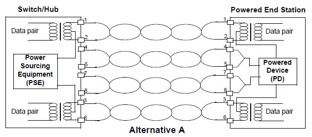
As shown in the following figure, a PSE can supply power to a PD through signal wire pairs. Because DC and data frequency does not interfere with each other, electric current and data can be transmitted through the same wire pair. For electric cables, this is a kind of "multiplexing". Wires 1 and 2 are connected to form a positive (or negative) polarity, and wires 3 and 6 are connected to form a negative (or positive) polarity.

Figure 12-1 Alternative A Power Supply Mode with 10BASE-T and 100BASE-TX
Power supply through idle wire pairs (Alternative B)
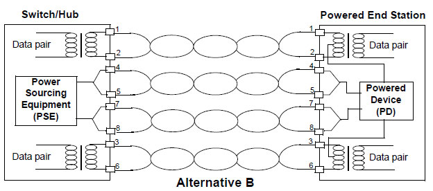
As shown in the following figure, a PSE can supply power to a PD through idle wire pairs. Wires 4 and 5 are connected to form a positive polarity, and wires 7 and 8 are connected to form a negative polarity.

Figure 12-2 Alternative B Power Supply Mode with 10BASE-T and 100BASE-TX
According to IEEE802.3af, standard PDs must support both power supply through signal wire pairs and power supply through idle wire pairs, while PSEs need only support either of the two modes.
 Switch
 Wifi - Access Point
 Firewall
 Router
 Module Quang
![Module Quang Cisco]() Module Quang Cisco
Module Quang Cisco![Module quang HPE]() Module quang HPE
Module quang HPE![Module quang Maipu]() Module quang Maipu
Module quang Maipu![Module quang Brocade]() Module quang Brocade
Module quang Brocade![Module quang Fortinet]() Module quang Fortinet
Module quang Fortinet![Module quang Aruba]() Module quang Aruba
Module quang Aruba![Module quang OEM]() Module quang OEM
Module quang OEM![Module quang Juniper]() Module quang Juniper
Module quang Juniper![Module quang Dell]() Module quang Dell
Module quang Dell![Module quang Palo Alto]() Module quang Palo Alto
Module quang Palo Alto![Module quang Huawei]() Module quang Huawei
Module quang Huawei![Module quang Arista]() Module quang Arista
Module quang Arista![Module quang F5]() Module quang F5
Module quang F5![Module quang H3C]() Module quang H3C
Module quang H3C![Module Quang Allied Telesis]() Module Quang Allied Telesis
Module Quang Allied Telesis![Module quang SonicWall]() Module quang SonicWall
Module quang SonicWall![Module quang Mikrotik]() Module quang Mikrotik
Module quang Mikrotik![Module quang Handar]() Module quang Handar
Module quang Handar Máy chủ (Server)
 Thiết bị lưu trữ (SAN, NAS)
 Load Balancing
 Video Conferencing
 Phụ kiện máy chủ
 Thiết Bị IoT
 Phụ Kiện Mạng


.png)


