Network Requirements
- Configure the BFD coordination between devices. When the main line is faulty, services can be quickly switched to the backup line.
- Device1, Device2, and Device3 are the Level-2 routers in the same area, Area 10. Configure the BFD on Device1 and Device3 to initiate a session. When the line between Device1 and Device3 disconnects, Device1 can perform switching quickly and learn the 10.1.1.1/24 routing from Device2.
Network Topology
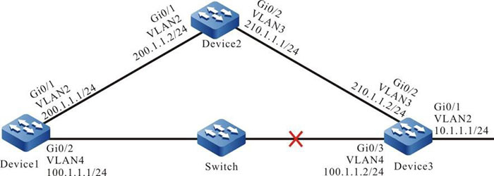
Figure 9–6 Networking of the IS-IS coordinating with the BFD
Configuration Steps
Step 1: Configure the IP address of the interfaces. (Omitted)
Step 2: Configure the IS-IS and enable the process on the interface.
#Configure the IS-IS process as 100, area number as 10, and type as Level-2 and enable the process on the interface on Device1.
|
Device1#configure terminal
Device1(config)#router isis 100
Device1(config-isis)#net 10.0000.0000.0001.00
Device1(config-isis)#is-type level-2
Device1(config-isis)#metric-style wide
Device1(config-isis)#exit
Device1(config)#interface vlan2
Device1(config-if-vlan2)#ip router isis 100
Device1(config-if- vlan2)#exit
Device1(config)#interface vlan4
Device1(config-if-vlan4)#ip router isis 100
Device1(config-if-vlan4)#exit
|
#Configure the IS-IS process as 100, area number as 10, and type as Level-2 and enable the process on the interface on Device2.
|
Device2#configure terminal
Device2(config)#router isis 100
Device2(config-isis)#net 10.0000.0000.0002.00
Device2(config-isis)#is-type level-2
Device2(config-isis)#metric-style wide
Device2(config-isis)#exit
Device2(config)#interface vlan2
Device2(config-if-vlan2)#ip router isis 100
Device2(config-if-vlan2)#exit
Device2(config)#interface vlan3
Device2(config-if-vlan3)#ip router isis 100
Device2(config-if-vlan3)#exit
|
#Configure the IS-IS process as 100, area number as 10, and type as Level-2 and enable the process on the interface on Device3.
|
Device3#configure terminal
Device3(config)#router isis 100
Device3(config-isis)#net 10.0000.0000.0003.00
Device3(config-isis)#is-type level-2
Device3(config-isis)#metric-style wide
Device3(config-isis)#exit
Device3(config)#interface vlan2
Device3(config-if-vlan2)#ip router isis 100
Device3(config-if-vlan2)#exit
Device3(config)#interface vlan3
Device3(config-if-vlan3)#ip router isis 100
Device3(config-if-vlan3)#exit
Device3(config)#interface vlan4
Device3(config-if-vlan4)#ip router isis 100
Device3(config-if-vlan4)#exit
|
#View the routing information of Device1. Device1 preferentially chooses the routing 10.1.1.0/24 advertised by Device3.
Device1#show ip route
Codes: C - connected, S - static, R - RIP, O - OSPF, OE-OSPF External, M - Management
       D - Redirect, E - IRMP, EX - IRMP external, o - SNSP, B - BGP, i-IS-IS

Gateway of last resort is not set

i 10.1.1.0/24 [115/20] via 100.1.1.2, 00:00:15, vlan4
C 100.1.1.0/24 is directly connected, 00:09:15, vlan4
C 127.0.0.0/8 is directly connected, 253:58:17, lo0
C 200.1.1.0/24 is directly connected, 00:11:29, vlan2
i 210.1.1.0/24 [115/20] via 100.1.1.2, 00:00:15, vlan4
               [115/20] via 200.1.1.2, 00:00:15, vlan2

Device1#show isis ipv4 route
IS-IS Instance 100, VRF Kernel, IPv4 routes table (Counter 4):
L2 10.1.1.0/24, flags none, metric 20, from learned, installed
     via 100.1.1.2, vlan4, neighbor 0000.0000.0003
L2 100.1.1.0/24, flags none, metric 10, from network connected
     via 0.0.0.0, vlan4
L2 200.1.1.0/24, flags none, metric 10, from network connected
     via 0.0.0.0, vlan2
L2 210.1.1.0/24, flags none, metric 20, from learned, installed
     via 100.1.1.2, vlan4, neighbor 0000.0000.0003
     via 200.1.1.2, vlan2, neighbor 0000.0000.0002
Step 3: Configure the BFD.
#Enable the BFD on the interface of Device1.
|
Device1(config)#bfd fast-detect
Device1(config)#interface vlan4
Device1(config-if-vlan4)#isis bfd
Device1(config-if-vlan4)#exit
|
#Enable the BFD on the Device3 interface.
|
Device3(config)#bfd fast-detect
Device3(config)#interface vlan4
Device3(config-if-vlan4)#isis bfd
Device3(config-if-vlan4)#exit
|
#View the BFD information of Device1.
Device1#show bfd session
OurAddr     NeighAddr    LD/RD  State Holddown   interface
100.1.1.2	100.1.1.1    1/1    UP    5000       vlan4
Step 4: Check the result.
#When the line between Device1 and Device3 is faulty, the BFD quickly detects the fault and informs the fault to the IS-IS. The ISIS switches the routing to Device2 for communication. View the routing table of Device1.
Device1#show ip route
Codes: C - connected, S - static, R - RIP, O - OSPF, OE-OSPF External, M - Management
       D - Redirect, E - IRMP, EX - IRMP external, o - SNSP, B - BGP, i-IS-IS

Gateway of last resort is not set

i 10.1.1.0/24 [115/30] via 200.1.1.2, 00:00:14, vlan2
C 127.0.0.0/8 is directly connected, 112:55:25, lo0
C 200.1.1.0/24 is directly connected, 101:20:08, vlan2

Device1#show isis ipv4 route
IS-IS Instance 100, VRF Kernel, IPv4 routes table (Counter 2):
L2 10.1.1.0/24, flags none, metric 30, from l earned, installed
     via 200.1.1.2, vlan2, neighbor 0000.0000.0003
L2 200.1.1.0/24, flags none, metric 20, from network connected
     via 0.0.0.0, vlan2
#It can be viewed that the data flow from Device1 to the 10.1.1.0/24 network segment priors to Device2.
 Switch


