Network Requirements
- Intranet users CE1 and CE2, and CE3 and CE4 communicate with each other through the carrier network. CE1 and CE2 uses the Intranet VLAN2, CE3 and CE4 uses Intranet VLAN3, and PE1 and PE2 are two edge devices in the carrier network.
- 1:1 VLAN mapping is configured on PE1 and PE2. Then, CE1 and CE2 can communicate with each other through VLAN00 of the carrier public network, CE3 and CE4 can communicate with each other through VLAN101 of the carrier public network, and the packets that are transmitted in the carrier public network contain two layers of tags.
Network Topology
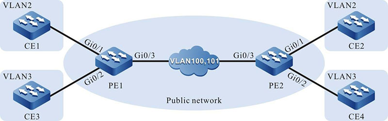
Figure 4-3 Configuring 1:1 VLAN Mapping
Configuration Steps
Step 1: Configure PE1.
#On PE1, create VLAN2-VLAN3 and VLAN100-VLAN101.
|
PE1#configure terminal
PE1(config)#vlan 2-3,100-101
|
#On PE1, configure the link type of port gigabitethernet0/1 to Trunk and allow services of VLAN2 and VLAN100 to pass, and set PVID to 1.
|
PE1(config)#interface gigabitethernet 0/1
PE1(config-if-gigabitethernet0/1)#switchport mode trunk
PE1(config-if-gigabitethernet0/1)#switchport trunk allowed vlan add 2,100
PE1(config-if-gigabitethernet0/1)#switchport trunk pvid vlan 1
PE1(config-if-gigabitethernet0/1)#exit
|
#On PE1, configure the link type of port gigabitethernet0/2 to Trunk and allow services of VLAN3 and VLAN101 to pass, and set PVID to 1.
|
PE1(config)#interface gigabitethernet 0/2
PE1(config-if-gigabitethernet0/2)#switchport mode trunk
PE1(config-if-gigabitethernet0/2)#switchport trunk allowed vlan add 3,101
PE1(config-if-gigabitethernet0/2)#switchport trunk pvid vlan 1
PE1(config-if-gigabitethernet0/2)#exit
|
#On PE1, configure the link type of port gigabitethernet0/3 to Trunk and allow services of VLAN100 and VLAN101 to pass, and set PVID to 1.
|
PE1(config)#interface gigabitethernet 0/3
PE1(config-if-gigabitethernet0/3)#switchport mode trunk
PE1(config-if-gigabitethernet0/3)#switchport trunk allowed vlan add 100,101
PE1(config-if-gigabitethernet0/3)#switchport trunk pvid vlan 1
PE1(config-if-gigabitethernet0/3)#exit
|
#On port gigabitethernet0/1 of PE1, configure the 1:1 VLAN mapping function so that the data of VLAN2 is changed to VLAN100.
|
PE1(config)#interface gigabitethernet 0/1
PE1(config-if-gigabitethernet0/1)#vlan dot1q-tunnel enable
PE1(config-if-gigabitethernet0/1)#vlan dot1q-tunnel mapping 2 100
PE1(config-if-gigabitethernet0/1)#exit
|
#On port gigabitethernet0/2 of PE1, configure the 1:1 VLAN mapping function so that the data of VLAN3 is changed to VLAN101.
|
PE1(config)#interface gigabitethernet 0/2
PE1(config-if-gigabitethernet0/2)#vlan dot1q-tunnel enable
PE1(config-if-gigabitethernet0/2)# vlan dot1q-tunnel mapping 3 101
PE1(config-if-gigabitethernet0/2)#exit
|
#On PE1, query the information about 1:1 VLAN mapping entries.
PE1#show vlan dot1q-tunnel mapping
-----------------------  ------------VLAN DOT1Q-TUNNEL MAPPING----------------  -------------
Interface VlanId Count        Former VlanId              Mapping VlanId             Former
-----------------------  --------------------  -------------------------------  -------------
gi0/1                        2                        100                              1
gi0/2                        3                        101                              1
Step 2: Configure PE2.
#On PE2, create VLAN2-VLAN3 and VLAN100-VLAN101.
|
PE2#configure terminal
PE2(config)#vlan 2-3,100-101
|
#On PE2, configure the link type of port gigabitethernet0/1 to Trunk and allow services of VLAN2 and VLAN100 to pass, and set PVID to 1.
|
PE2(config)#interface gigabitethernet 0/1
PE2(config-if-gigabitethernet0/1)#switchport mode trunk
PE2(config-if-gigabitethernet0/1)#switchport trunk allowed vlan add 2,100
PE2(config-if-gigabitethernet0/1)#switchport trunk pvid vlan 1
PE2(config-if-gigabitethernet0/1)#exit
|
#On PE2, configure the link type of port gigabitethernet0/2 to Trunk and allow services of VLAN3 and VLAN101 to pass, and set PVID to 1.
|
PE2(config)#interface gigabitethernet 0/2
PE2(config-if-gigabitethernet0/2)#switchport mode trunk
PE2(config-if-gigabitethernet0/2)#switchport trunk allowed vlan add 3,101
PE2(config-if-gigabitethernet0/2)#switchport trunk pvid vlan 1
PE2(config-if-gigabitethernet0/2)#exit
|
#On PE2, configure the link type of port gigabitethernet0/3 to Trunk and allow services of VLAN100 and VLAN101 to pass, and set PVID to 1.
|
PE2(config)#interface gigabitethernet 0/3
PE2(config-if-gigabitethernet0/3)#switchport mode trunk
PE2(config-if-gigabitethernet0/3)#switchport trunk allowed vlan add 100,101
PE2(config-if-gigabitethernet0/3)#switchport trunk pvid vlan 1
PE2(config-if-gigabitethernet0/3)#exit
|
#On port gigabitethernet0/1 of PE2, configure the 1:1 VLAN mapping function so that the data of VLAN2 is changed to VLAN100.
|
PE2(config)#interface gigabitethernet 0/1
PE2(config-if-gigabitethernet0/1)#vlan dot1q-tunnel enable
PE2(config-if-gigabitethernet0/1)#vlan dot1q-tunnel mapping 2 100
PE2(config-if-gigabitethernet0/1)#exit
|
#On port gigabitethernet0/2 of PE2, configure the 1:1 VLAN mapping function so that the data of VLAN3 is changed to VLAN101.
|
PE2(config)#interface gigabitethernet 0/2
PE2(config-if-gigabitethernet0/2)#vlan dot1q-tunnel enable
PE2(config-if-gigabitethernet0/2)#vlan dot1q-tunnel mapping 3 101
PE2(config-if-gigabitethernet0/2)#exit
|
#On PE2, query the information about 1:1 VLAN mapping entries.
PE1#show vlan dot1q-tunnel mapping
-----------------------  ------------VLAN DOT1Q-TUNNEL MAPPING----------------  -------------
Interface VlanId Count        Former VlanId              Mapping VlanId             Former
-----------------------  --------------------  -------------------------------  -------------
gi0/1                        2                        100                              1
gi0/2                        3                        101                              1
Step 3: Check the result.
#Through PE1 and PE2, the services of Intranet users CE1 and CE2 can be transmitted in VLAN100 of the carrier network with one layer of tags. Through PE1 and PE2, the services of Intranet users CE3 and CE4 can be transmitted in VLAN101 of the carrier network with one layer of tags.
 Switch


