Network Requirements
- On Device1, configure two static routes to the segment 192::3/128: one is reachable via Device2, and the other is reachable via Device3. Device1 first uses the line with Device3 to forward the packet.
- On Device1, configure one static recursive route to the segment 2001:4::/64, and the gateway address is the loopback interface address of Device3 192::3. After the line between Device1 and Device3 fails, the route can switch to Device2 for communication.
Network Topology
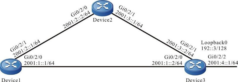
Figure 4-4 Networking for configuring IPv6 static recursive route
Configuration Steps
Step 1: Configure the IPv6 address of the interface (omitted).
Step 2: Configure the IPv6 static route.
#Configure Device1.
|
Device1#configure terminal
Device1(config)#ipv6 route 192::3/128 2001:1::2
Device1(config)#ipv6 route 192::3/128 2001:2::2 10
|
#Configure Device2.
|
Device2#configure terminal
Device2(config)#ipv6 route 192::3/128 2001:3::2
|
Step 3: Configure the IPv6 static recursive route.
# Configure Device1.
|
Device1(config)#ipv6 route 2001:4::/64 192::3
|
#Query the IPv6 route table of Device1.
Device1#show ipv6 route
Codes: C - Connected, L - Local, S - static, R - RIP, B - BGP, i-ISIS
       U - Per-user Static route
       O - OSPF, OE-OSPF External, M - Management

L ::1/128 [0/0]
     via ::, 2w0d:03:12:46, lo0
S 192::3/128 [1/10]
     via 2001:1::2, 00:04:54, gigabitethernet0/2/0
C  2001:1::/64 [0/0]
     via ::, 00:22:47, gigabitethernet0/2/0
L 2001:1::1/128 [0/0]
     via ::, 00:22:45, lo0 C 2001:2::/64 [0/0]
     via ::, 00:16:16, gigabitethernet0/2/1
L 2001:2::1/128 [0/0]
     via ::, 00:16:15, lo0
S 2001:4::/64 [1/10]
     via 192::3, 00:00:43, gigabitethernet0/2/0
In the IPv6 route table, you can see that the gateway address of the route 2001:4::/64 is 192::3, the egress interface is gigabitethernet0/2/0, and the route depends on the route 192::3/128.
Step 4: Check the result.
#After the line between Device1 and Device3 fails, query the IPv6 route table of Device1.
Device1#show ipv6 route
Codes: C - Connected, L - Local, S - static, R - RIP, B - BGP, i-ISIS
       U - Per-user Static route
       O - OSPF, OE-OSPF External, M - Management

L ::1/128 [0/0]
     via ::, 2w0d:03:17:48, lo0
S 192::3/128 [10/10]
     via 2001:2::2, 00:00:06, gigabitethernet0/2/1
C  2001:2::/64 [0/0]
     via ::, 00:21:18, gigabitethernet0/2/1
L 2001:2::1/128 [0/0]
     via ::, 00:21:17, lo0
S 2001:4::/64 [1/10]
     via 192::3, 00:00:06, gigabitethernet0/2/1
Compared with the route table of step 3, you can see that the egress interface of the route 2001:4::/64 is gigabitethernet0/2/1, indicating that the route already switches to Device2 for communication.
 Switch


