Network Requirements
- The whole network runs the IPv6 PIM-SM protocol.
- Receiver is one receiver of Device3 stub network.
- Device2 is C-BSR and C-RP.
- On Device2 and Device3, control for the multicast source, making PC only receive the multicast service packet sent by Multicast Server 1.
- Run MLDv2 between Device3 and the stub network.
Network Topology
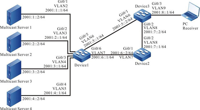
Figure 11-3 Networking of configuring IPv6 PIM-SM multicast forwarding control
Configuration Steps
Step 1: Configure VLAN, and add the port to the corresponding VLAN (omitted).
Step 2: Configure the IPv6 address of the interface. (omitted)
Step 3: Enable the unicast route protocol OSPFv3 so that all devices in the network can communicate with each other.
#Configure Device1.
|
Device1#configure terminal
Device1(config)#ipv6 router ospf 100
Device1(config-ospf6)#router-id 1.1.1.1
Device1(config-ospf6)#exit
Device1(config)#interface vlan2
Device1(config-if-vlan2)#ipv6 router ospf 100 area 0
Device1(config-if-vlan2)#exit
Device1(config)#interface vlan3
Device1(config-if-vlan3)#ipv6 router ospf 100 area 0
Device1(config-if-vlan3)#exit
Device1(config)#interface vlan4
Device1(config-if-vlan4)#ipv6 router ospf 100 area 0
Device1(config-if-vlan4)#exit
Device1(config)#interface vlan5
Device1(config-if-vlan5)#ipv6 router ospf 100 area 0
Device1(config-if-vlan5)#exit
Device1(config)#interface vlan6
Device1(config-if-vlan6)#ipv6 router ospf 100 area 0
Device1(config-if-vlan6)#exit
Device1(config)#interface vlan7
Device1(config-if-vlan7)#ipv6 router ospf 100 area 0
Device1(config-if-vlan7)#exit
|
#Configure Device2.
|
Device2#configure terminal
Device2(config)#ipv6 router ospf 100
Device2(config-ospf6)#router-id 2.2.2.2
Device2(config-ospf6)#exit
Device2(config)#interface vlan7
Device2(config-if-vlan7)#ipv6 router ospf 100 area 0
Device2(config-if-vlan7)#exit
Device2(config)#interface vlan8
Device2(config-if-vlan8)#ipv6 router ospf 100 area 0
Device2(config-if-vlan8)#exit
|
#Configure Device3.
|
Device3#configure terminal
Device3(config)#ipv6 router ospf 100
Device3(config-ospf6)#router-id 3.3.3.3
Device3(config-ospf6)#exit
Device3(config)#interface vlan6
Device3(config-if-vlan6)#ipv6 router ospf 100 area 0
Device3(config-if-vlan6)#exit
Device3(config)#interface vlan8
Device3(config-if-vlan8)#ipv6 router ospf 100 area 0
Device3(config-if-vlan8)#exit
Device3(config)#interface vlan9
Device3(config-if-vlan9)#ipv6 router ospf 100 area 0
Device3(config-if-vlan9)#exit
|
#View the route table of Device3.
Device3#show ipv6 route
Codes: C - Connected, L - Local, S - static, R - RIP, B - BGP, i-ISIS
       U - Per-user Static route
       O - OSPF, OE-OSPF External, M - Management


L ::1/128 [0/0]
     via ::, 3w2d:05:13:23, lo0
O 2001:1::/64 [110/2]
     via fe80::201:7aff:fe62:bb7e, 00:00:24, vlan6
O  2001:2::/64 [110/2]
     via fe80::201:7aff:fe62:bb7e, 00:00:24, vlan6
O  2001:3::/64 [110/2]
     via fe80::201:7aff:fe62:bb7e, 00:00:24, vlan6
O  2001:4::/64 [110/2]
     via fe80::201:7aff:fe62:bb7e, 00:00:24, vlan6
C  2001:5::/64 [0/0]
     via ::, 00:01:52, vlan6
L 2001:5::2/128 [0/0]
     via ::, 00:01:50, lo0
O 2001:6::/64 [110/2] via fe80::201:7aff:fe62:bb7e, 00:00:24, vlan6
              [110/2] via fe80::201:7aff:fec0:525a, 00:00:24, vlan8
C  2001:7::/64 [0/0]
     via ::, 00:01:25, vlan8
L 2001:7::2/128 [0/0]
     via ::, 00:01:24, lo0
C 2001:8::/64 [0/0]
     via ::, 00:01:16, vlan9
L 2001:8::1/128 [0/0]
     via ::, 00:01:14, lo0

-
The viewing method of Device1 and device2 is the same as that of Device3, so the viewing process is omitted.
Step 4: Globally enable the IPv6 multicast forwarding and enable the multicast protocol IPv6 PIM-SM on the interface.
#Configure Device1.
Globally enable the IPv6 multicast forwarding and enable the multicast protocol IPv6 PIM-SM on the related interfaces.
|
Device1(config)#ipv6 multicast-routing
Device1(config)#interface vlan2
Device1(config-if-vlan2)#ipv6 pim sparse-mode
Device1(config-if-vlan2)#exit
Device1(config)#interface vlan3
Device1(config-if-vlan3)#ipv6 pim sparse-mode
Device1(config-if-vlan3)#exit
Device1(config)#interface vlan4
Device1(config-if-vlan4)#ipv6 pim sparse-mode
Device1(config-if-vlan4)#exit
Device1(config)#interface vlan5
Device1(config-if-vlan5)#ipv6 pim sparse-mode
Device1(config-if-vlan5)#exit
Device1(config)#interface vlan6
Device1(config-if-vlan6)#ipv6 pim sparse-mode
Device1(config-if-vlan6)#exit
Device1(config)#interface vlan7
Device1(config-if-vlan7)#ipv6 pim sparse-mode
Device1(config-if-vlan7)#exit
|
#Configure Device2.
Globally enable the IPv6 multicast forwarding and enable the multicast protocol IPv6 PIM-SM on the related interfaces.
|
Device2(config)#ipv6 multicast-routing
Device2(config)#interface vlan7
Device2(config-if-vlan7)#ipv6 pim sparse-mode
Device2(config-if-vlan7)#exit
Device2(config)#interface vlan8
Device2(config-if-vlan8)#ipv6 pim sparse-mode
Device2(config-if-vlan8)#exit
|
#Configure Device3.
Globally enable the IPv6 multicast forwarding and enable the multicast protocol IPv6 PIM-SM on the related interfaces.
|
Device3(config)#ipv6 multicast-routing
Device3(config)#interface vlan6
Device3(config-if-vlan6)#ipv6 pim sparse-mode
Device3(config-if-vlan6)#exit
Device3(config)#interface vlan8
Device3(config-if-vlan8)#ipv6 pim sparse-mode
Device3(config-if-vlan8)#exit
Device3(config)#interface vlan9
Device3(config-if-vlan9)#ipv6 pim sparse-mode
Device3(config-if-vlan9)#exit
|
#View the information of the interface enabled with the IPv6 PIM-SM protocol on Device3 and the IPv6 PIM-SM neighbor information.
Device3#show ipv6 pim interface
PIM6 Interface Table:
PIM6 VRF Name: Default
Total 4 Interface entries
Total 0 External Interface entry
Total 0 Sparse-Dense Mode Interface entry

Interface    VIF Ver/ VIF Nbr DR   BSR   CISCO   Neighbor
                 Index Mode Flag Count Pri Border Neighbor Filter
register_vif0   2     v2/S UP
Address : fe80::201:7aff:fe5e:6d2d Global Address: ::

vlan6      1     v2/S UP   1     1    FALSE FALSE
Address : fe80::201:7aff:fe5e:6d2d        Global Address: 2001:5::2               DR: fe80::201:7aff:fe62:bb7e

vlan8      4     v2/S UP   1     1    FALSE FALSE
Address : fe80::201:7aff:fe5e:6d2e        Global Address: 2001:7::2               DR: fe80::201:7aff:fec0:525a

vlan9      3     v2/S UP   0     1    FALSE FALSE
Address : fe80::201:7aff:fe5e:6d2f        Global Address: 2001:8::1               DR: fe80::201:7aff:fe5e:6d2f


Device3#show ipv6 pim neighbor
PIM6 Neighbor Table:
PIM6 VRF Name: Default
Total 2 Neighbor entries

Neighbor                  Interface    Uptime/Expires     Ver DR
Address                                                   Priority/Mode
fe80::201:7aff:fe62:bb7e  vlan6        00:07:08/00:01:25  v2 1 / DR
fe80::201:7aff:fec0:525a  vlan8        00:00:18/00:01:27  v2 1 / DR
-
The viewing method of Device1 and device2 is the same as that of Device3, so the viewing process is omitted.
Step 5: Configure gigabitethernet0/0/0 of Device2 as the C-BSR and C-RP of the whole network and the multicast group range of the C-RP service is FF00::/8.
#Configure Device2.
|
Device2(config)#ipv6 pim bsr-candidate vlan7
Device2(config)#ipv6 pim rp-candidate vlan7
|
#View the BSR and RP information of Device3.
Device3#show ipv6 pim bsr-router
PIM6v2 Bootstrap information
PIM6 VRF Name: Default
  BSR address: 2001:6::2
  BSR Priority: 0
  Hash mask length: 126
  Up time: 00:00:21
  Expiry time: 00:01:54
  Role: Non-candidate BSR
State: Accept Preferred

Device3#show ipv6 pim rp mapping
PIM6 Group-to-RP Mappings Table:
PIM6 VRF Name: Default
Total 1 RP set entry
Total 1 RP entry

  Group(s): ff00::/8
  RP count: 1
    RP: 2001:6::2
      Info source: 2001:6::2, via bootstrap, priority 192
      Up time: 00:00:28
      Expiry time: 00:02:02
-
The viewing method of Device1 and device2 is the same as that of Device3, so the viewing process is omitted.
Step 6: On Device2 and Device3, control for the multicast source, making PC only receive the multicast service packet sent by Multicast Server 1.
#On Device2, configure the accepted register message access list, filtering the register message of Multicast Server 4.
|
Device2(config)#ipv6 access-list extended 7001
Device2(config-std-nacl)#deny ipv6 host 2001:4::2 any
Device2(config-std-nacl)#permit ipv6 any any
Device2(config-std-nacl)#commit
Device2(config-std-nacl)#exit
Device2(config)#ipv6 pim accept-register list 7001
|
#On interface valn6 and vlan8 of Device3, configure the ingress IPv6 acl, filtering the multicast service packets of Multicast Server 3.
|
Device3(config)#ipv6 access-list extended 7001
Device3(config-v6-list)#deny ipv6 host 2001:3::2 any
Device3(config-v6-list)#permit ipv6 any any
Device3(config-v6-list)#commit
Device3(config-v6-list)#exit
Device3(config)#interface vlan6
Device3(config-if-vlan6)#ipv6 access-group 7001 in
Device3(config-if-vlan6)#exit
Device3(config)#interface vlan8
Device3(config-if-vlan8)#ipv6 access-group 7001 in
Device3(config-if-vlan8)#exit
|
#On interface vlan9 of Device3, configure the ingress IPv6 acl, filtering the multicast service packets of Multicast Server 2.
|
Device3(config)#ipv6 access-list extended 7002
Device3(config-v6-list)#deny ipv6 host 2001:2::2 any
Device3(config-v6-list)#permit ipv6 any any
Device3(config-v6-list)#commit
Device3(config-v6-list)#exit
Device3(config)#interface vlan9
Device3(config-if-vlan9)#ipv6 access-group 7002 out
Device3(config-if-vlan9)#exit
|
Step 7: Check the result.
#PC sends the MLDv2 member relation report to add to multicast group FF10::1.
# Multicast Server 1, Multicast Server 2, Multicast Server 3, and Multicast Server 4 all send the multicast packets of multicast group FF10::1.
#View the multicast member table of Device3.
Device3#show ipv6 mld groups
MLD Connected Group Membership
Total 1 Connected Groups
Group   Interface  Uptime   Expires   V1-Expires Last Reporter
ff10::1 vlan9      00:35:31 00:03:31  not used   fe80::210:94ff:fe00:1
#View the multicast route table of Device3.
Device3#show ipv6 pim mroute
IP Multicast Routing Table:
PIM6 VRF Name: Default
Total 0 (*,*,RP) entry
Total 1 (*,G) entry
Total 2 (S,G) entries
Total 2 (S,G,rpt) entries
Total 0 FCR entry
Up timer/Expiry timer

(*, ff10::1)
Up time: 00:04:25
RP: 2001:6::2
RPF nbr: fe80::201:7aff:fec0:525a
RPF idx: vlan8
Flags:
  JOIN DESIRED
Upstream State: JOINED
  Local interface list:
    vlan9
  Joined interface list:
  Asserted interface list:


(2001:1::2, ff10::1)
Up time: 00:03:33
KAT time: 00:01:51
RPF nbr: fe80::201:7aff:fe62:bb7e
RPF idx: vlan6
SPT bit: TRUE
Flags:
  JOIN DESIRED
Upstream State: JOINED
  Local interface list:
  Joined interface list:
  Asserted interface list:
  Outgoing interface list:
    vlan9
  Packet count 159075

(2001:1::2, ff10::1, rpt)
Up time: 00:03:33
RP: 2001:6::2
Flags:
  RPT JOIN DESIRED
  PRUNE DESIRED
  RPF SGRPT XG EQUAL
Upstream State: PRUNED
  Local interface list:
  Pruned interface list:
  Outgoing interface list:
    vlan9

(2001:2::2, ff10::1)
Up time: 00:03:33
KAT time: 00:01:51
RPF nbr: fe80::201:7aff:fe62:bb7e
RPF idx: vlan6
SPT bit: TRUE
Flags:
  JOIN DESIRED
Upstream State: JOINED
  Local interface list:
  Joined interface list:
  Asserted interface list:
  Outgoing interface list:
    vlan9
  Packet count 156062

(2001:2::2, ff10::1, rpt)
Up time: 00:03:33
RP: 2001:6::2
Flags:
  RPT JOIN DESIRED
  PRUNE DESIRED
  RPF SGRPT XG EQUAL
Upstream State: PRUNED
  Local interface list:
  Pruned interface list:
  Outgoing interface list:
    vlan9
-
The viewing method of Device1 and device2 is the same as that of Device3, so the viewing process is omitted.
#View the matching of IPv6 ACL on Device2.
Device2#show ipv6 access-list 7001
ipv6 access-list extended 7001
 10 deny ipv6 host 2001:4::2 any    14 matches
 20 permit ipv6 any any    51 matches
#View the matching of IPv6 ACL on Device3.
Device3#show ipv6 access-list 7001
ipv6 access-list extended 7001
 10 deny ipv6 host 2001:3::2 any    10760 matches
 20 permit ipv6 any any    4089685 matches

Device3#show ipv6 access-list 7002
ipv6 access-list extended 7002
 10 deny ipv6 host 2001:2::2 any    2046914 matches
 20 permit ipv6 any any    2049595 matches
#PC end can only receive the multicast service packets sent by Multicast Server 1.

-
When performing the multicast source control, you’d better first configure the multicast source control and then on-demand multicast source, because by default, after receiving the multicast service packet, the receiving end DR performs the SPT switching. If first on-demanding multicast source and then performing the multicast forwarding control, the multicast forwarding control does not take function. To prevent the multicast forwarding control from not taking function, you can configure not permitting SPT switching on the receiving end DR.
 Switch


