Network Requirements
- Device1 and Device2 belong to two VBRP groups at the same time; Device1 is Active in group1 and Standby in group2; Device2 is Standby in group1 and Active in group2.
- PC1 forwards data via Device1 and PC2 forwards data via Device2, realizing the load balance.
Network Topology
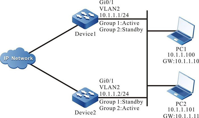
Figure 7-4 Networking of VBRP load balance
Configuration Steps
Step 1: Configure VLAN and add the port to the corresponding VLAN.(Omitted)
Step 2: Configure the IP address of the interface.(Omitted)
Step 3: Create VBRP group1.
#Configure the virtual IP address of VBRP group 1 on Device1 as 10.1.1.10, enable the preemption function, and configure the priority as 110.
|
Device1#configure terminal
Device1(config)#interface vlan 2
Device1(config-if-vlan2)#standby 1 ip 10.1.1.10
Device1(config-if-vlan2)#standby 1 preempt
Device1(config-if-vlan2)#standby 1 priority 110
|
#Configure the virtual IP address of VBRP group1 on Device2 as 10.1.1.10 and enable the preemption function.
|
Device2#configure terminal
Device2(config)#interface vlan 2
Device2(config-if-vlan2)#standby 1 ip 10.1.1.10
Device2(config-if-vlan2)#standby 1 preempt
|
Step 4: Create VBRP group2.
#Configure the virtual IP address of VBRP group 2 on Device1 as 10.1.1.11, and enable the preemption function.
|
Device1(config)#interface vlan 2
Device1(config-if-vlan2)#standby 2 ip 10.1.1.11
Device1(config-if-vlan2)#standby 2 preempt
|
#Configure the virtual IP address of VBRP group 1 on Device2 as 10.1.1.11, enable the preemption function, and configure the priority as 120.
|
Device2(config)#interface vlan 2
Device2(config-if-vlan2)#standby 2 ip 10.1.1.11
Device2(config-if-vlan2)#standby 2 preempt
Device2(config-if-vlan2)#standby 2 priority 120
|
Step 5: Check the result.
#View the status of VBRP in group 1 and group 2 on Device1.
Device1#show standby
Interface vlan2
  Primary address 10.1.1.1, state up
Group 1
  State is Active
  Virtual IP address is 10.1.1.10
  Refer to local IP prefix 10.1.1.1/24
  Local virtual MAC address is 0000.0c07.ac01
  Current MAC type VMAC, installed into HW
  Hello time 3 sec, hold time 10 sec
    Next hello sent in 0.633348 secs
  Preemption enabled, delay 0 sec
  Active router is local
  Standby router is 10.1.1.2, priority 100 (expires in 7.83370 secs)
  Priority 110 (configured 110)
Group 2
  State is Standby
  Virtual IP address is 10.1.1.11
  Refer to local IP prefix 10.1.1.1/24
  Local virtual MAC address is 0000.0c07.ac02
  Current MAC type VMAC
  Hello time 3 sec, hold time 10 sec
    Next hello sent in 0.950002 secs
  Preemption enabled, delay 0 sec
  Active router is 10.1.1.2, priority 120 (expires in 7.300028 secs)
  Standby router is local
  Priority 100 (configured 100)
#View the status of VBRP in group 1 and group 2 on Device2.
Device2#show standby
Interface vlan2
  Primary address 10.1.1.2, state up
Group 1
  State is Standby
  Virtual IP address is 10.1.1.10
  Refer to local IP prefix 10.1.1.2/24
  Local virtual MAC address is 0000.0c07.ac01
  Current MAC type VMAC
  Hello time 3 sec, hold time 10 sec
    Next hello sent in 0.600016 secs
  Preemption enabled, delay 0 sec
  Active router is 10.1.1.1, priority 110 (expires in 7.700012 secs)
  Standby router is local
  Priority 100 (configured 100)
Group 2
  State is Active
  Virtual IP address is 10.1.1.11
  Refer to local IP prefix 10.1.1.2/24
  Local virtual MAC address is 0000.0c07.ac02
  Current MAC type VMAC, installed into HW
  Hello time 3 sec, hold time 10 sec
    Next hello sent in 0.816674 secs
  Preemption enabled, delay 0 sec
  Active router is local
  Standby router is 10.1.1.1, priority 100 (expires in 8.33332 secs)
  Priority 120 (configured 120)
We can see that Device1 serves as Active of VBRP group1 and Standby of VBRP group2. In contrast with Device1, Device2 serves as Active of VBRP group 2 and Standby of VBRP group 1. When one device fails, two PCs forward data via the other device. This realizes the load balance and backup for each other.
 Switch


